Emerson Process Management GmbH & Co. OHG2-12
X-STREAM XEFD
Instruction Manual
HASXEDE-IM-EX
03/2012
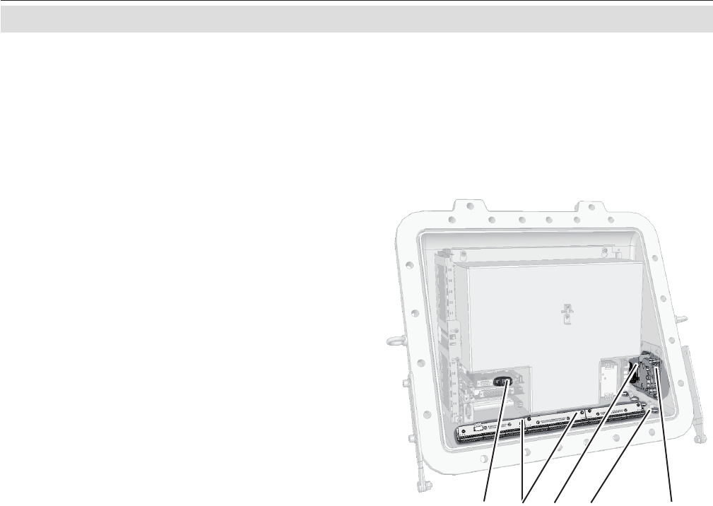
Fig. 2-8: Allocation of terminals
1 Terminals for signal cables
2 Power EMI lter
3 4 cable entries for power and signal cables
4 Power terminals with integrated fuses
5 Ethernet and USB connectors
2.4 Installation - Electrical
Unused entries during installation have to be
provided with plugs.
Installation under CSA certication requires
the use of approved conduits and suitable
metric-to-NPT adaptors. .
Both plugs and cable entries must be installed
properly and xed by applying the prescribed
torque.
The instrument provides internal screw termi-
nals for connecting power and signal cables.
This requires opening the instrument during
installation:
• Unsrew the 20 screws located on the
enclosure ange.
• Flap down the cover part to gain access
to the analyzer inside.
Inside the enclosure, keep all cables as short
as possible to prevent from interferences.
ATEX approved analyzers provide 4 cable
entries (M20 x 1.5) and are shipped with a
set of 4 plugs.
Owner of such analyzers are responsible to
provide suitable cable glands according all ap-e suitable cable glands according all ap-
plicable standards (e. g. IEC/EN 60079-14).
See maintenance section of this manual for
recommended cable glands.
1 42 35


