


Emerson Process Management GmbH & Co. OHG3-2
X-STREAM XEFD
Instruction Manual
HASXEDE-IM-EX
03/2012
3.2 Leak Test
3.2 Performing a Leak Test
Max. pressure 7.25 psig
(500 mbar)!
Multi channel instruments:
Analyzers with parallel tubing
require separate leak tests for
each gas path !
To achieve best and proper measuring results
you must ensure the gas path system does
not have leaks.
The following procedure describes how to
perform a leak test with focus on the instru-
ment.
The gas path system should be leak tested
at least on a bimonthly basis and after main-
tenance, replacement or repair of gas path
parts.
Note!
We recommend to include external equip-
ment (e.g. cooler, dust lters, etc.) into a leak
test!
Required tools
• U-turn manometer for max. 1.45 psi
(100 mbar)
• Stop valve
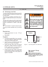
Procedure
• Connect the water lled u-turn manome-
ter to the analyzer‘s sample gas output
(disconnect external gas lines).
• Install the stop valve between gas input
tting and a nitrogen (N
2
) supply.
• Open the stop valve until the internal
gas path is under pressure of approx.
0.725 psi/50 mbar (corresponding to
19.7 inch/500 mm water column)
• Close the stop valve. After a short time
for the water to balance, the water level
must not change over a time period of
approx. 5 minutes!
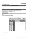
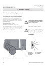
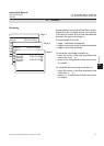
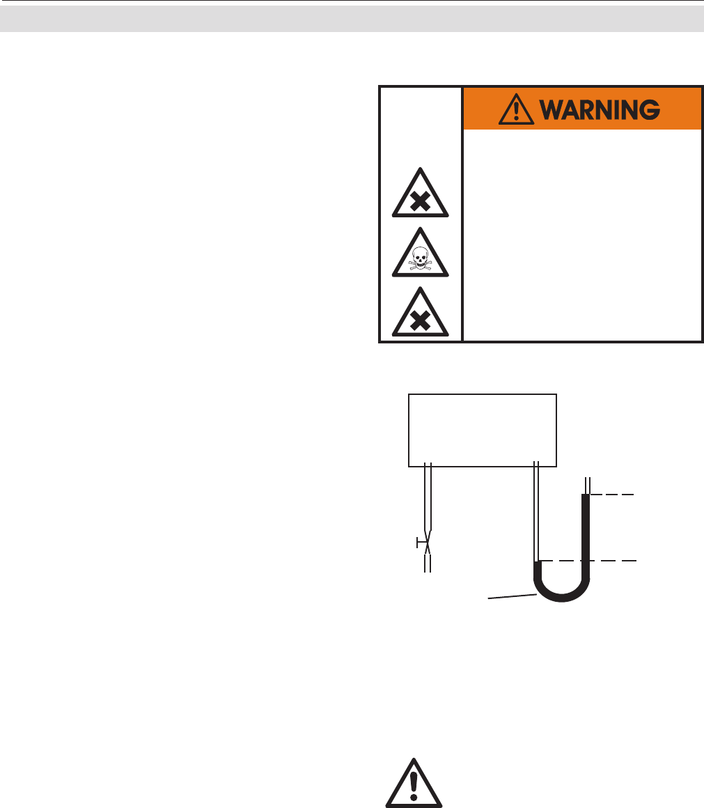
Analyzer
overpressure
approx.
0.725 psi /
50 mbar
stop
valve
Water
Fig. 3-1: Leak Testing With U-Turn Manometer
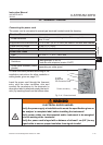
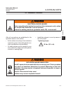
HAZARD FROM GASES
Before opening gas paths
they must be purged with
ambient air or neutral gas (N2)
to avoid hazards caused by
toxic, ammable, explosive
or harmful to health sample
gas components!