


Emerson Process Management GmbH & Co. OHG2-4
X-STREAM XEFD
Instruction Manual
HASXEDE-IM-EX
03/2012
1
2
3
4
5
5
6
7
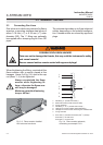
2.3 Installation - Gas Lines
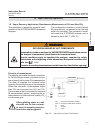
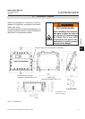
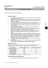
2.3 Connecting Gas Lines
Gas inlets and outlets are protected by ame
arrestors, supporting stainless steel pipes of
either 3.18 mm (
1
⁄8“) or 6.35 mm (
1
⁄4“) outer
diameter (OD). The
1
⁄4“ tting may optionally
be supplied with a clamping ring for 6 mm OD
pipes.
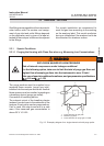
Fig. 2-3: Flame arrestor installed
into instrument enclosure
1: Gas tting
1
⁄8“ (inside instrument) *
)
2: M18 male threat (inside enclosure wall)
3: O-ring (optional)
4: Gas tting
1
⁄4“ or
1
⁄8“ (outside instrument) *
)
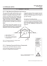
5: Hexagon for counter holding while thightening
6: Hexagon for wrench when mounting into a M18 threat
7: O-ring shoulder
*) FA 01 with
1
⁄4“ (outside instrument) and
1
⁄8“ (inside)
FA 02 with
1
⁄4“ at both ends
FA 03 with
1
⁄8“ at both ends
Fig. 2-4: Flame arrestor elements,
considering as example FA 01
When thightening the tting, counterhold the
ame arrestor with a wrench placed at the
hexagon (items 5 of g. 2-4) next to the cap
nut (items 1, 4) to be tightened.
Always counterhold the ame
arrestor while thightening t-
tings; otherwise the ame arre-
stor may be damaged!
Maximum permitted fastening
torque: 40 Nm!
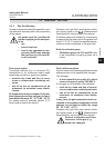
The instrument provides up to 8 gas inlets and
outlets, depending on the ordered congura-
tion. Unused entries are closed by approved
plugs.
POSSIBLE EXPLOSION HAZARD
Take care not to damage the threats, this may void the instrument´s safety
and cause hazards!
Ensure unused entries remain sealed with approved plugs!