Emerson Process Management GmbH & Co. OHG 1-19
1
Techn. Description
X-STREAM XEFD
Instruction Manual
HASXEDE-IM-EX
03/2012
1.9 Vapor Recovery Application
1.9 Vapor Recovery Application (Simultaneous Measurement of CH
4
and Non-CH
4
)
This application is served by a special con-
guration of the X-STREAM XEFD ameproof
analyzer.
EXPLOSION HAZARD BY HOT COMPONENTS
Temperatures inside an analyzer for VAPOR RECOVERY applications exceed
the analyzer‘s temperature classication for hazardous areas!
Special conditions apply to handling this analyzer, consider the safety
instructions at the beginning of this manual and the special conditions for
safe use
(
1-5 )!
Consider the waiting time statement on the front door label before opening!
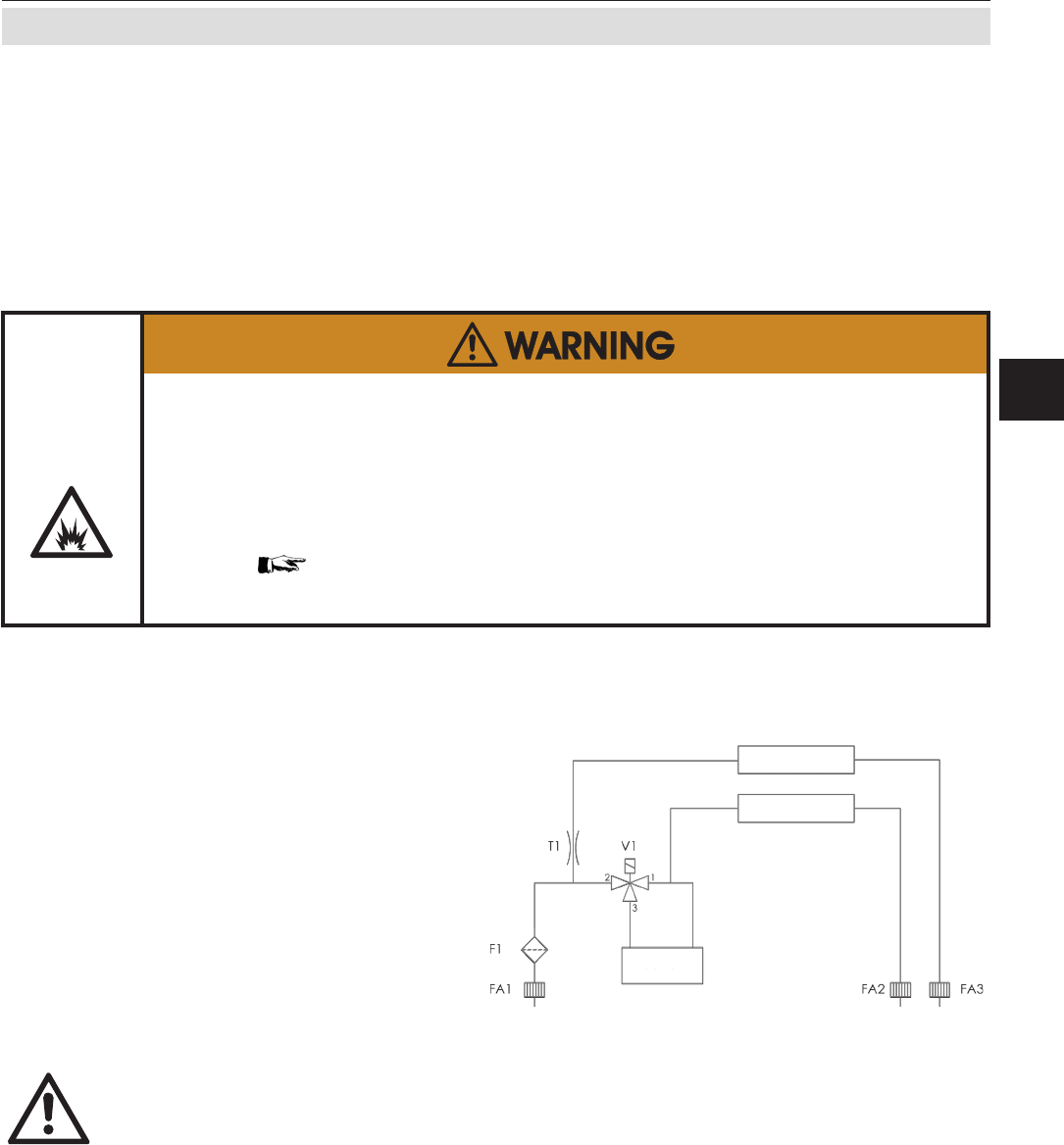
FA1: Analyzer‘s inlet ame arrestor
FA2...3: Analyzer‘s outlet ame arrestors
F1: Filter
T1: Throttle
V1: Valve
The conguration consists of a dual channel
IR measurement, connected to the inlet and
outlet of a converter. This converter is instal-
led inside the X-STREAM analyzer and is
heated to about 280 °C (536 °F).
Fig. 1-7: Vapor Recovery Gas Flow Diagram
)$ )$ )$
&XWWHU
)
7
9
&+&+
&+&+
%H]HLFKQHU
'HVLJQDWRU
%HQHQQXQJ
'HVFULSWLRQ
)
)LOWHU)LOWHU
)$)$
)$
)ODPPHQVSHUUHQ
)ODPH$UUHVWRU
7
'URVVHO7KURWWOH
9
9HQWLO9DOYH
)
(
'
&
$
%
$
6FKXW]YHUPHUN',1EHDFKWHQ
&
(PHUVRQ3URFHVV0DQDJHPHQW*PEK&R2+*
(:2
JDVIORZGLDJUDPFXWWHU
(:2
0DVWDEVFDOH
%HQHQQXQJ'HVFULSWLRQ
=HLFKQXQJ1U'UDZLQJ1R
(UVI
%HDUE
9HUDQW
'DWXP
1DPH
5RKPD1RUPVL]HVWDQGDUG
+DOE]HXJVHPLILQLVKHGSDUWV
:HUNVWRIIPDWHULDO
=XVW
1DPH
'DWXP
bQGHUXQJ
VKHHW
%ODWW
(UVG
%O
*HZLFKWZHLJKW
1RUP
,QGH[
',1P.
WROHUDQ]
$OOJHPHLQ
,62
.DQWHQ
7ROHULHUXQJ,62
0HWKRGH(
*DVIOXVVVFKHPD&XWWHU
,62
Converter
CH2: non-CH
4
CH1: CH
4
Principle of measurement
The sample gas is taken towards a converter.
At it‘s inlet the gas stream is divided into two:
one is directly fed to a non-CH
4
measurement.
The other is supplied to a solenoid valve,
normally forwarding the gas to the converter.
Within the converter, hydrocarbons higher
than CH
4
are converted into H
2
O and CO
2
.
The converter outlet is connected to a second
IR measurement system, analyzing the re-
maing amount of hydrocarbons (mainly CH
4
)
in the sample gas.
After switching power on, wait
about 50 min. for the converter
to reach its operating tempera-
ture before applying gases!


