


Operation Using
a Programmable Logic Controller (PLC)
Digital Inputs
• Safety Interlock: This normally open contact works
like a soft emergency stop button. If the ProMix
PD2K reads the input as CLOSED it interrupts
system operation and removes power from the
pumps regardless of the current operating mode.
If the input is read as OPEN, the system operates
normally
NOTE: This digital input is always enabled.
Do not toggle this input to put the system into
Standby mode.
• Gun Trigger: This normally open (maintained)
contact provides a signal to the system to indicate
whether or not a spray device is triggered. This
input provides timing for alarm functions and also
drives the flow control algorithm. If the input is
OPEN the system operates as though the spray
device is off. The input must be maintained
CLOSED to signal that the spray device is
triggered.
NOTE: The Gun Trigger discrete input must be
enabled via Configure Screen 5 on the ADM. If it
is set to ‘Network’ the discrete input is ignored and
the spray device trigger signal is handled via the
network communications.
If enabled, it is imperative that this signal be sent
any time the spray device is triggered. Without the
signal, the flow control features will not work.
Analog Inputs
Flow Control Set Point: When enabled, this 4-20mA
signal input is used to set and adjust the operating
flow control set point. The ProMix PD2K scales the
set point linearly from 0 to the Max Set Point setting
(see System Screen 5, page 71).
Examples
,
• In Flow Cont
rol Mode: If the Max Set Point is 500
cc/min, a 4m
A signal is 0 cc/min and a 20mA signal
is 500 cc/mi
n.
• In Pressur
e Control Mode: If the Max Set Point is
500 psi, a 4
mA signal is 0 psi and a 20mA signal
is 500 psi.
NOTE: The Flow Control discrete input must be
enabled via Configure Screen 5 on the ADM. If
set to ‘Network’ the discrete input is ignored and
set point adjustment is handled via the network
communications.
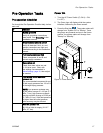
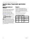
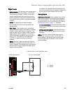
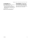
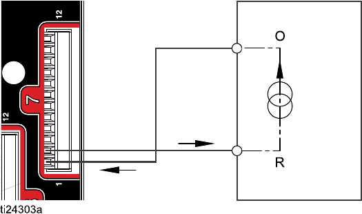
4–20 mA
Flow Control Set Point Input
PD2K Discrete Input
PLC (4–20 MA Signal)
Figur
e10
O = Output
R=Return
332564B 25