


Operation Using
a Programmable Logic Controller (PLC)
Network Commu
nication - Dynamic Command Structure (DCS)
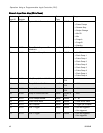
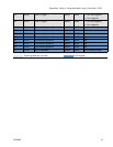
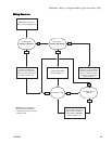
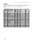
Dynamic Command Description
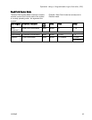
The Dynamic Command Structure (DCS) is used to 1) access data that requires some form of
argument(s) or 2) consolidate data that requires multiple registers. The DCS uses a static set of network
communication input and output registers (see Network Input Data Map (Write/Read), page 40 and
Network Output Data Map (Read Only), page 33.
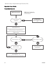
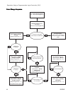
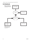
Use the foll
owing sequence for the DCS.
1. Write the appropriate command arguments to INPUT REGISTERS 14 – 20. These commands may be
written sequentially or sent all at once.
2. Once all arguments have been passed, write the command ID to INPUT REGISTER 21.
3. TheProMixPD2Kwillrespondtoavalidcommandbywritinga2(Acknowledge) to OUTPUT REGISTER
28.
4. The ProMix PD2K will write appropriate return values to OUTPUT REGISTERS 29 – 36.
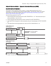
INPUT REGISTER 14
ProMix PD2K Inputs
(PLC Outputs)
ProMix PD2K Outputs
(PLC Inputs)
[arg_0]
INPUT REGISTER 14+n [arg_n]
INPUT REGISTER 21
OUTPUT REGISTER 28
OUTPUT REGISTER 29
OUTPUT REGISTER 29+n
[id]
ACK = 2
[rtn_0]
[rtn_n]
Can be written together
or sequentially.
Figure
13 Dynamic Command Structure Timing
332564B
47