


Operation Using
a Programmable Logic Controller (PLC)
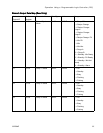
INPUT REGISTER 01: Pump Flush Sequence/Prime
Material Selection
ThePumpFlush
Sequence/Prime Material Selection
register is us
ed in conjunction with the Flush/Prime
Pump Command r
egister (see INPUT REGISTER 02
below) to inde
pendently prime or flush an inactive
pump.
• Write a value between 1 and 5 if flushing a pump.
• Write a value between 1 and 30 if priming a Color
pump.
• Writeavaluebetween31and34ifpriminga
Catalyst pump.
NOTE: It is important that the user know which
material is assigned to each pump. An invalid
selection will be ignored by the ProMix PD2K.
INPUT REG
ISTER 02: Flush/Prime Pump Command
The Flush/Prime Pump Command register is used in
conjunction with the Pump Flush Sequence/Prime
Material Selection register (see INPUT REGISTER
01) to independently prime or flush an inactive pump.
The desired pump MUST be in Standby mode.
Confirm by reading the corresponding Pump Status
output register (see OUTPUT REGISTERS 01 – 04).
If an invalid Flush Sequence or invalid material
number is written to the Pump Flush Sequence/Prime
Material Selection register then the Flush/Prime
command will be ignored. The user must know
what material is assigned to each pump. (See
Color Change Kits Instruction Manual 332455 for
color/catalyst pump mapping.)
NOTE:
If two pumps are currently mixing and an
inact
ive pump is commanded to flush or prime it will
conti
nue its operation to completion without affecting
the s
ystem mode status. When the mixing operation
is co
mplete, the system status will reflect Standby
mode
while the flushing/priming pump completes its
oper
ation.
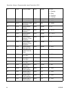
INPUT REGISTER 03: Mix (Pump 1) Control Set
Point
The Mix Contro
l Set Point register is used to set and
adjust the mix
ing fluid control set point. It also is used
as the fluid con
trol set point for pump 1 when running
a1Krecipe.It
can be changed at any time, and the
system will i
mmediately adjust to the new set point.
• If the system is configured for Flow Control this
value can be set between 5 and 1600 cc/min for a
2K recipe, and between 5 and 800 for a 1K recipe.
See Fluid Control on System Screen 5, page 71.
• If the system is configure for Pressure Control this
value can be set between 0 and the maximum
pump pressure in PSI. See Fluid Control on
System Screen 5, page 71.
NOTE: The Flow Control must be configured to
‘Network’ via System Screen 5 on the ADM. If set
to ‘Discrete’ this register is ignored and set point
adjustment is handled via the discrete input. See
Analog Inputs, page 25.
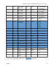
INPUT REG
ISTER 04: Pump 2 Control Set Point
INPUT REGISTER 05: Pump 3 Control Set Point
INPUT REGISTER 06: Pump 4 Control Set Point
These r
egisters are not used.
INPUT REGISTER 07: Go to Recipe Number
The Go to Recipe Number register is used as a
queue for the next recipe to be loaded when a recipe
change is initiated. A number between 0 and 60 can
be written to this register. However, a recipe must be
enabled via the ADM before it can be loaded. See
Recipe Screen, page 72.
NOTE
: Writing to this register does not trigger a recipe
chan
ge.
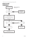
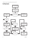
See Color Change Sequence, page 44.
332564B 37