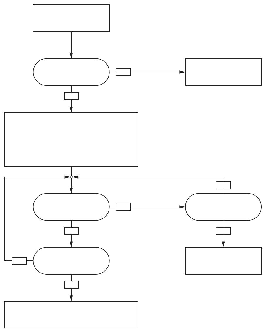
Operation Using
a Programmable Logic Controller (PLC)
Operation Flo
w Charts
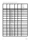
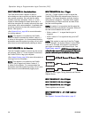
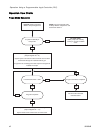
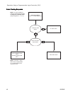
Purge Mode Sequence
YES
YES
YES YES
NO
NO
NO
NO
Purge A System Command
Write ‘6’ to Input Register 00
Is system in Standby or
Pumps Off?
Is solvent flow switch 1 ON?
Purge time expired?
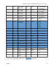
System Mode = Standby: Mix Not Ready
(Output Register 00 = ‘13’)
System closes color solvent valve at remote stack.
Purge no flow timeout expired?
No solvent flow detected.
Generate alarm.
System Mode = Purge A
(Output Register 00 = ‘9’)
System opens color solvent valve at remote stack to allow
solvent flow through mix manifold and out gun.
Purge time set according to the flush sequence assigned to
material A in recipe.
No action taken.
Either pumps are currently
running or an alarm condition
exists.
NOTE: Purge B command works
similarly with the catalyst lines and
solvent flow switch 2.
4
2
332564B


