


3. Be sure the torch and work cable rubber coverings
are free of cuts and cracks that allow high fre-
quency leakage. Cables with high natural rubber
content, such as Lincoln Stable-Arc
®
better resist
high frequency leakage than neoprene and other
synthetic rubber insulated cables.
4. Keep the torch in good repair and all connections
tight to reduce high frequency leakage.
5. The work terminal must be connected to a ground
within ten feet of the welder, using one of the fol-
lowing methods.
a) A metal underground water pipe in direct con-
tact with the earth for ten feet or more.
b) A 3/4” (19mm) galvanized pipe or a 5/8”
(16mm) solid galvanized iron, steel or copper
rod driven at least eight feet into the ground.
The ground should be securely made and the
grounding cable should be as short as possible
using cable of the same size as the work cable, or
larger. Grounding to the building frame electrical
conduit or a long pipe system can result in re-radi-
ation, effectively making these members radiating
antennas.
6. Keep all access panels and covers securely in
place.
7. All electrical conductors within 50 ft (15.2m) of the
welder should be enclosed in grounded, rigid
metallic conduit or equivalent shielding. Flexible
metallic conduit is generally not suitable.
8. When the welder is enclosed in a metal buidling,
several good earth driven electrical grounds (as in
5 (b) above) around the periphery of the building
are recommended.
Failure to observe these recommended installation
procedures can cause radio or TV interference
problems and result in unsatisfactory welding per-
formance resulting from lost high frequency
power.
INPUT CONNECTIONS
Be sure the voltage, phase, and frequency of the input
power is as specified on the rating plate, located on
the front of the machine.
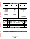
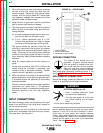
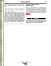
Welder supply line entry provision is in the case rear
panel with a removable cover over the input connec-
tion panel area. See Figure A.1.
GROUND CONNECTION
The frame of the welder must be
grounded. A ground terminal marked
with the symbol is located at the bot-
tom of the input box for this purpose.
See your local and national electrical
codes for proper grounding methods.
Also follow other grounding instructions given in the
section “High Frequency Interference Protection.”
INPUT SUPPLY CONNECTION
Be sure the voltage, phase, and frequency of the input
power is as specified on the welder nameplate.
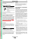
ELECTRIC SHOCK can kill.
• Have a qualified electrician install
and service this equipment.
• Turn the input power off at the fuse
box before working on this equip-
ment.
• Do not touch electrically hot parts.
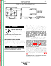
Have a qualified electrician connect the input power
leads to L1 and L2 of the input contactor in accor-
dance with all local codes and national electrical
codes. Use a single phase line or one phase of a two
or three phase line. Refer to the connection diagram
located on the inside of the cover of the Reconnect
Panel. Also see Figure A.2.
INSTALLATION
A-4 A-4
SQUARE WAVE TIG 355
Return to Section TOC Return to Section TOC Return to Section TOC Return to Section TOC
Return to Master TOC Return to Master TOC Return to Master TOC Return to Master TOC
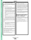
FIGURE A.1 – REAR PANEL
1. WARNING DECAL
2. INPUT POWER ENTRY
3. RECONNECT PANEL COVER
WARNING
2
3