


F-79 F-79
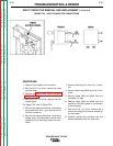
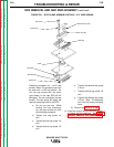
SCR REMOVAL AND AND REPLACEMENT (continued)
TROUBLESHOOTING & REPAIR
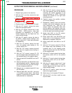
The unclamping and clamping procedure out-
lined below is critical for the prevention of iner-
nal SCR damage. Failure to follow this proce-
dure may result in subsequent damage of the
SCR. Handle all SCRs with care.
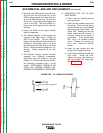
PROCEDURE
1. Perform the Output Rectifier Removal
and Replacement procedure.
2. With the 1/2” wrench, alternately loosen the
heat sink nuts 1/2 turn each until the heat
sinks are loose. Remove the nuts and leaf
spring. IT IS RECOMMENDED THAT NEW
HARDWARE, LEAF SPRING AND HOUS-
ING BE USED FOR REASSEMBLY.
3. Remove the old SCR.
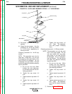
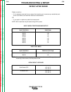
4. With a puffy knife or similar tool, clean the
area on the heat sink around the SCR
mounting surface. DO NOT SCRATCH THE
SCR MOUNTING SURFACE.
5. Polish each heat sink’s mounting surface
using No. 000 fine steel wool. Wipe the
surface clean with a lint-free cloth or paper
towel.
6. Inspect the mounting surfaces of each new
SCR. Remove all burrs and wipe clean. Do
not use steel wool or any abrasive cleanser
on the SCR mounting surfaces.
7. Apply a thin (0.001” to 0.003”) layer of PEN-
ETROX A-13 (Lincoln Electric #E2529) or
PENETROX A, heat sink compound, to
each heat sink’s SCR mounting surface.
Use care to prevent foreign material conta-
mination of the SCR-to-heat sink junction.
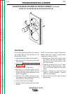
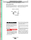
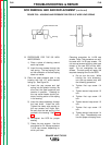
SPECIAL INSTRUCTIONS
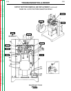
Before disassembling the output rectifier, note
which heat sink the outer metal ring of the
power SCR is mounted toward. Also note the
positioning of the gate lead of the SCR. Failure
to reinstall the new SCR in the same orienta-
tion as the original may result in subsequent
damage to the new SCR and other compo-
nents of the welder. See Figure F.27.
SQUARE WAVE TIG 355
Return to Section TOC Return to Section TOC Return to Section TOC Return to Section TOC
Return to Master TOC Return to Master TOC Return to Master TOC Return to Master TOC
CAUTION
FIGURE F.27 - SCR DETAILS