


F-42 F-42
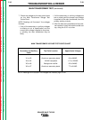
MAIN TRANSFORMER TEST (continued)
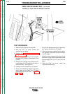
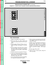
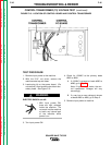
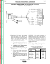
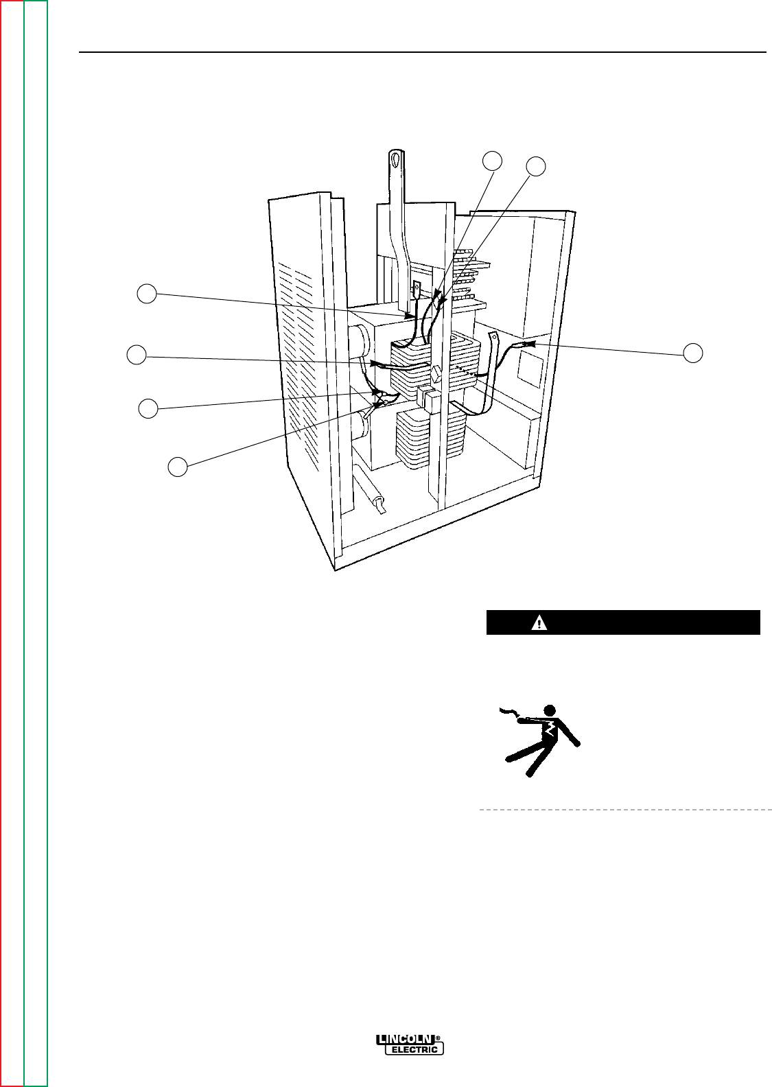
FIGURE F.12 - MAIN TRANSFORMER LOCATION AND WIRING DETAILS
TROUBLESHOOTING & REPAIR
TEST PROCEDURE
1. Remove input power to the machine.
2. With the 5/16" nut driver, remove the
machine top and sides.
3. Perform the power factor capacitor dis-
charge procedure.
4. Inspect the input contactor, reconnect
panel, and primary leads to the main trans-
former for loose or faulty connections.
5. Check the reconnect panel to make sure
that the single phase AC power supplied to
the machine is properly connected.
6. Locate leads X1 though X7. See Figure
F.12.
ELECTRIC SHOCK can kill.
• With input power ON, there are high volt-
ages inside the machine.
Do not reach into the
machine or touch any inter-
nal part of the machine while
power is on.
7. Turn on input power to the machine.
SQUARE WAVE TIG 355
Return to Section TOC Return to Section TOC Return to Section TOC Return to Section TOC
Return to Master TOC Return to Master TOC Return to Master TOC Return to Master TOC
WARNING
X5
X6
X2
X4
X3
X7
X1