


Return to Section TOC Return to Section TOC Return to Section TOC Return to Section TOC
Return to Master TOC Return to Master TOC Return to Master TOC Return to Master TOC
F-27 F-27
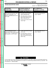
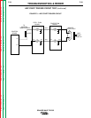
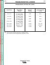
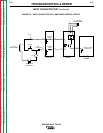
POWER BOARD VOLTAGE TEST CHART
TROUBLESHOOTING & REPAIR
SQUARE WAVE TIG 355
Check Points
IJ4 to 2J4
4J4 to 6J4
4J4 to 5J4
10J4 to 12J4
3J2(+) to 5J2
4J2(-) to 5J2
IJ2(+) to 2J2
Signals Being
Checked
AC supply voltage
from T5 transformer
AC supply voltage
from T5 transformer
AC supply voltage
from T5 transformer
AC supply voltage
from T5 transformer
Regulated +15VDC
Regulated -15VDC
Unregulated DC
Expected
Reading
10VAC
32VAC
16VAC
36VAC
+15VDC
-15VDC
+14VDC
Special Conditions
for Test
None
None
None
None
LED 1 ON
LED 2 ON
None
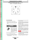
Note: LED 3 should be ON when gate signal is applied to SCR 1.
LED 4 should be ONE when gate signal is applied to SCR 4.