


F-45 F-45
CONTROL TRANSFORMER (T5) VOLTAGE TEST (continued)
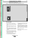
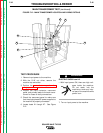
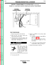
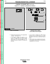
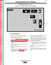
FIGURE F.13 - LOCATION OF CONTROL BOARD AND CONTROL TRANSFORMER
TROUBLESHOOTING & REPAIR
TEST PROCEDURE
1. Remove input power to the machine.
2. With the 5/16” nut driver, remove the
machine case top and sides.
3. Locate plug J4 on the power board. (Do
not remove.) Also locate the two black sec-
ondary leads. See Figure F.13.
ELECTRIC SHOCK can kill.
• With input power ON,
there are high voltages
inside the machine. Do
not reach into the machine
or touch any internal part
of the machine while
power is on.
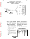
3. Turn input power ON.
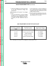
4. Check for 120VAC at the primary leads
#265 to #266.
A. If 120VAC is present at leads #265 to
#266, go to Step 7.
Note: If input voltage varies, the con-
trol transformer voltages will vary
accordingly.
B. If a very low or zero voltage is shown
at leads #265 to #266, go to Step 5.
5. Remove input power to machine.
SQUARE WAVE TIG 355
Return to Section TOC Return to Section TOC Return to Section TOC Return to Section TOC
Return to Master TOC Return to Master TOC Return to Master TOC Return to Master TOC
WARNING