


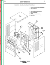
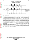
HIGH VOLTAGE
TRANSFORMER
CIRCUIT
REMOTE
RECEPTACLE
GAS/WATER
SOLENOIDS
FANS
115VAC
RECEPTACLE
INPUT
CONTACTOR
R
E
C
O
N
N
E
C
T
POWER
FACTOR
CAPACITORS
FEED - THRU
BOARD
CONTROL
BOARD
POWER
BOARD
SNUBBER
BOARD
MAIN
TRANSFORMER
AC
AC
DC-
DC+
POLARITY
SWITCH
SHUNT
C
H
O
K
E
BY-PASS
BOARDS
WORK
ELECTRODE
HI-FREQ
TRANSFORMER
PILOT
TRANSFORMER
START/
STOP
PANEL
SWITCHES
UPPER
CONTROL
PANEL
LOWER
CONTROL
PANEL
DISPLAY
BOARD
STATUS
BOARD
ELECTRODE SENSE
HIGH FREQUENCY SPARK
115VAC
INTERLOCK
HI-FREQ AND GAS/WATER
115VAC -
115VAC
CONTROL TRANSFORMER
INTERLOCK
ELECTRODE
SENSE
REMOTE
COMMANDS
GATE COMMANDS
HI-FREQ/
WATER/GAS
COMMANDS
INTERLOCK
115VAC
SCR
TRIGGER
15VDC
115VAC
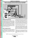
GENERAL DESCRIPTION
The Square Wave TIG 355 is a constant current, single
range square wave AC/DC TIG (GTAW) arc welding
power source with built-in high frequency stabilization.
It also has stick (SMAW) capability. The Square Wave
TIG 355 gives the operator full control of the welding
current plus the ability to preset weld and start cur-
rents. Preflow and postflow timers are included for
shielding gas and cooling water control. Altogether
the many features of the machine allow part or all of a
weld cycle to be preset or “programmed,” which sim-
plifies the TIG welding process.
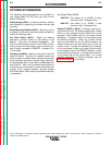
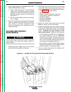
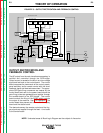
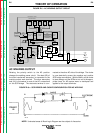
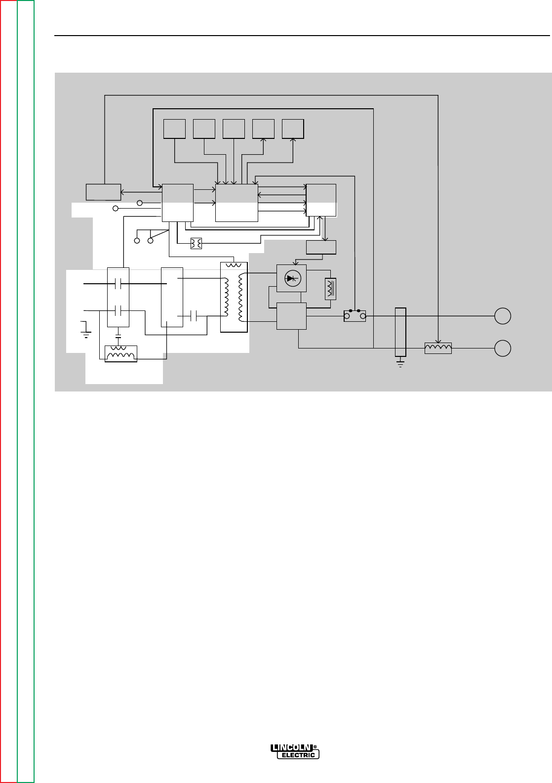
INPUT POWER CIRCUIT
The desired single-phase input power is connected to
the TIG 355 through an input contactor located in the
rear of the machine. The input power is also con-
nected directly to the pilot transformer, which supplies
115VAC for the input contactor interlock and start/
stop circuits.
A reconnect panel allows the user to configure the
pilot transformer, the power factor capacitors, and the
main transformer for the desired input voltage. This
AC input voltage is applied, through the input contac-
tor, to the primary of the main transformer. The power
factor correction capacitors are incorporated in the
primary circuit of the main transformer to help balance
the inductive nature of the TIG 355. The main trans-
former changes the high voltage, low current input
power to a low voltage, high current output.
In addition, the main transformer also has an isolated
115VAC auxiliary winding that supplies power to oper-
ate the cooling fans and offers 15 amps of auxiliary
power at the 115VAC receptacle. This 115VAC is also
applied, through the feed-thru board, to the power
board for high voltage and gas/water solenoid opera-
tion.
The control transformer primary is also powered by the
115VAC winding in the main transformer. The sec-
ondary voltages that are developed in the control
transformer supply power to the control and power
boards.
THEORY OF OPERATION
E-2 E-2
SQUARE WAVE TIG 355
Return to Section TOC Return to Section TOC Return to Section TOC Return to Section TOC
Return to Master TOC Return to Master TOC Return to Master TOC Return to Master TOC
FIGURE E.2 – INPUT VOLTAGE, CONTACTOR, RECONNECT PANEL, PILOT TRANSFORMER,
CONTROL TRANSFORMER, POWER FACTOR CAPACITORS AND MAIN TRANSFORMER
NOTE: Unshaded areas of Block Logic Diagram are the subject of discussion.