


Return to Section TOC Return to Section TOC Return to Section TOC Return to Section TOC
Return to Master TOC Return to Master TOC Return to Master TOC Return to Master TOC
OUTPUT CONNECTIONS
ELECTRIC SHOCK can kill.
• Keep the electrode holder, TIG
torch and cables insulation in
good condition and in place.
• Do not touch electrically live parts
or electrode with skin or wet
clothing.
• Insulate yourself from work and ground.
• Turn the power off pushbutton on the Square Wave
TIG 355 “off” before connecting or disconnecting
output cables or other equipment.
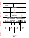
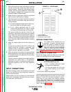
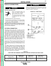
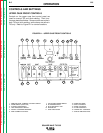
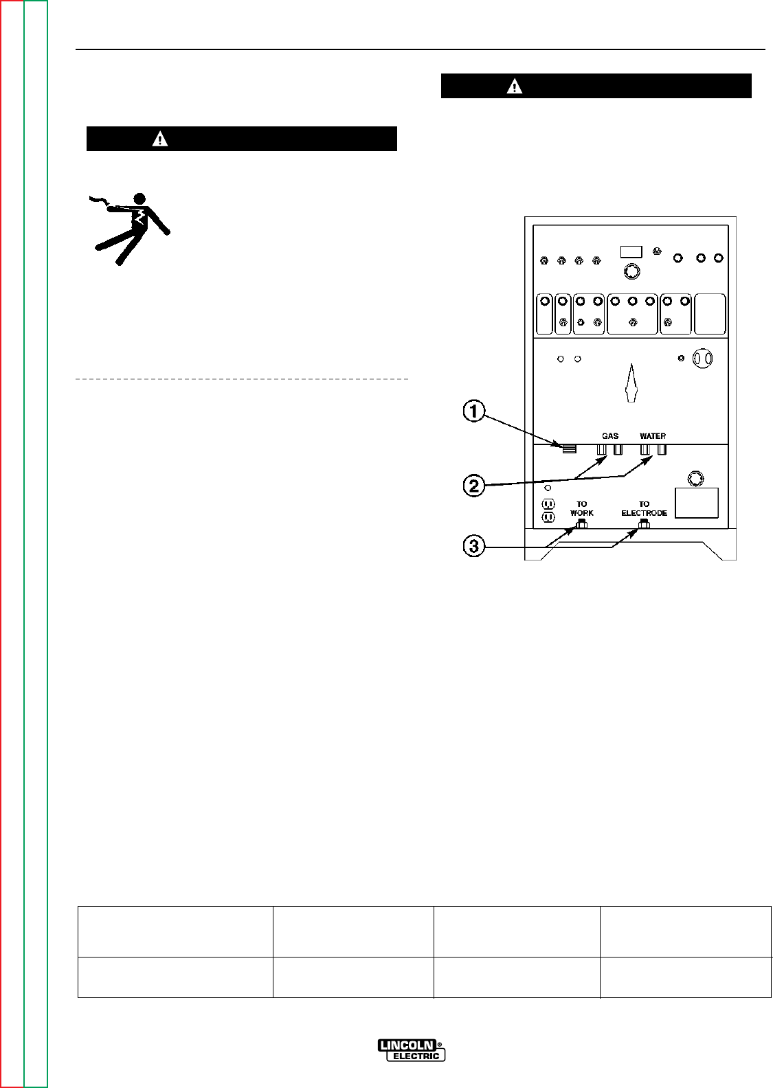
See Figure A.3 for the location of the work and elec-
trode terminals, the gas and optional water solenoids,
and the Remote Receptacle.
TIG TORCH CONNECTION
TIG welding torches come with 15 ft (4.6m) and 25 ft
(7.6m) cables. Use the shorter length whenever pos-
sible to minimize possible radio interference problems.
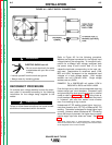
With power source off, connect the torch cable to the
“Electrode” terminal on the welder. Connect a sepa-
rate work cable to the “Work” terminal of the welder.
See Table A.3 for recommended work cable sizes.
Both work and electrode cables should be routed
through the cable strain relief holes provided in the
base directly below the welding ouput terminals.
Connect the TIG torch gas and water fittings to the
welder fittings. any torch with fittings that conform to
Compressed Gas Association (CGA) standards can be
used.
The welder fittings have the following threads: Gas
Inlet and Outlet: 5/8”-18 right-hand female; Water inlet
and Outlet: 5/8”-18 left-hand female. The cylinder of
inert shielding gas must be equipped with a pressure
regulator and flow meter. Install a hose between the
flow meter and gas inlet on the welder.
Observe the safety precautions necessary for handling
and using compressed gas containers. Contact your
supplier for specific information.
INSTALLATION
A-7 A-7
SQUARE WAVE TIG 355
1. REMOTE RECEPTACLE
2. WATER AND GAS
SOLENOIDS
3. WORK (LEFT) AND
ELECTRODE TERMINALS
WARNING
WARNING
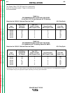
TABLE A.3
CABLE SIZES FOR COMBINED LENGTHS OF COPPER ELECTRODE AND WORK CABLE
Lengths up to 100 to 200 ft 200 to 250 ft
Machine Size 100 ft (30 m) (30 to 61 m) (61 to 76 m)
350 Amp
40% Duty Cycle #1 (45mm
2
) 1/0 (55mm
2
) 2/0 (70mm
2
)
FIGURE A.3 – FRONT PANEL