


Return to Section TOC Return to Section TOC Return to Section TOC Return to Section TOC
Return to Master TOC Return to Master TOC Return to Master TOC Return to Master TOC
F-81 F-81
TROUBLESHOOTING & REPAIR
SQUARE WAVE TIG 355
5) Re-inspect the SCR for proper
seating.
6) Clamp the cap screws. Use the
procedure for 1/4-28 cap screws
or 1/4-20 bolts, depending on
which you have.
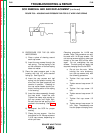
Clamping procedure for 1/4-28 cap
screws.
NOTE: This procedure can only be
used with 1/4-28 bolts. Do not use
bolts with any other type thread, or the
new SCR will be damaged. Do not
overtighten the cap screws. The leaf
spring will apply the required clamping
force to the SCR.
a. Do not turn the nuts. While
holding the nuts stationary,
turn the bolts only with the fol-
lowing procedure.
b. Tighten first cap screw 1/4
turn.
c. Tighten second cap screw 1/2
turn.
d. Tighten first cap screw 1/2
turn.
e. Tighten second cap screw 1/2
turn.
f. Tighten first cap screw 1/4
turn. Stop. The assembly
now has proper clamping
force.
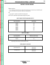
Clamping procedure for 1/4-20 cap screws.
NOTE: This procedure can only be used
with 1/4-20 cap screws. Do not
use cap screws with any other
type thread, or the new SCR will
be damaged. Do not overtighten
the cap screws. The leaf spring
will apply the required clamping
force to the SCR.
a. Do not turn the nuts. While
holding the nuts stationary,
turn the cap screws only with
the following procedure.
b. Tighten first cap screw 1/4
turn.
c. Tighten second cap screw 1/2
turn.
d. Tighten first cap screw 1/2
turn.
e. Tighten second cap screw 1/4
turn. Stop. The assembly
now has the proper clamping
force.
7) Perform the Active SCR Test.
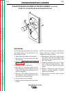
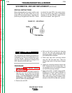
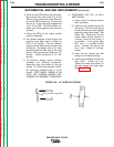
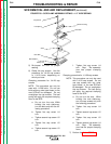
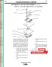
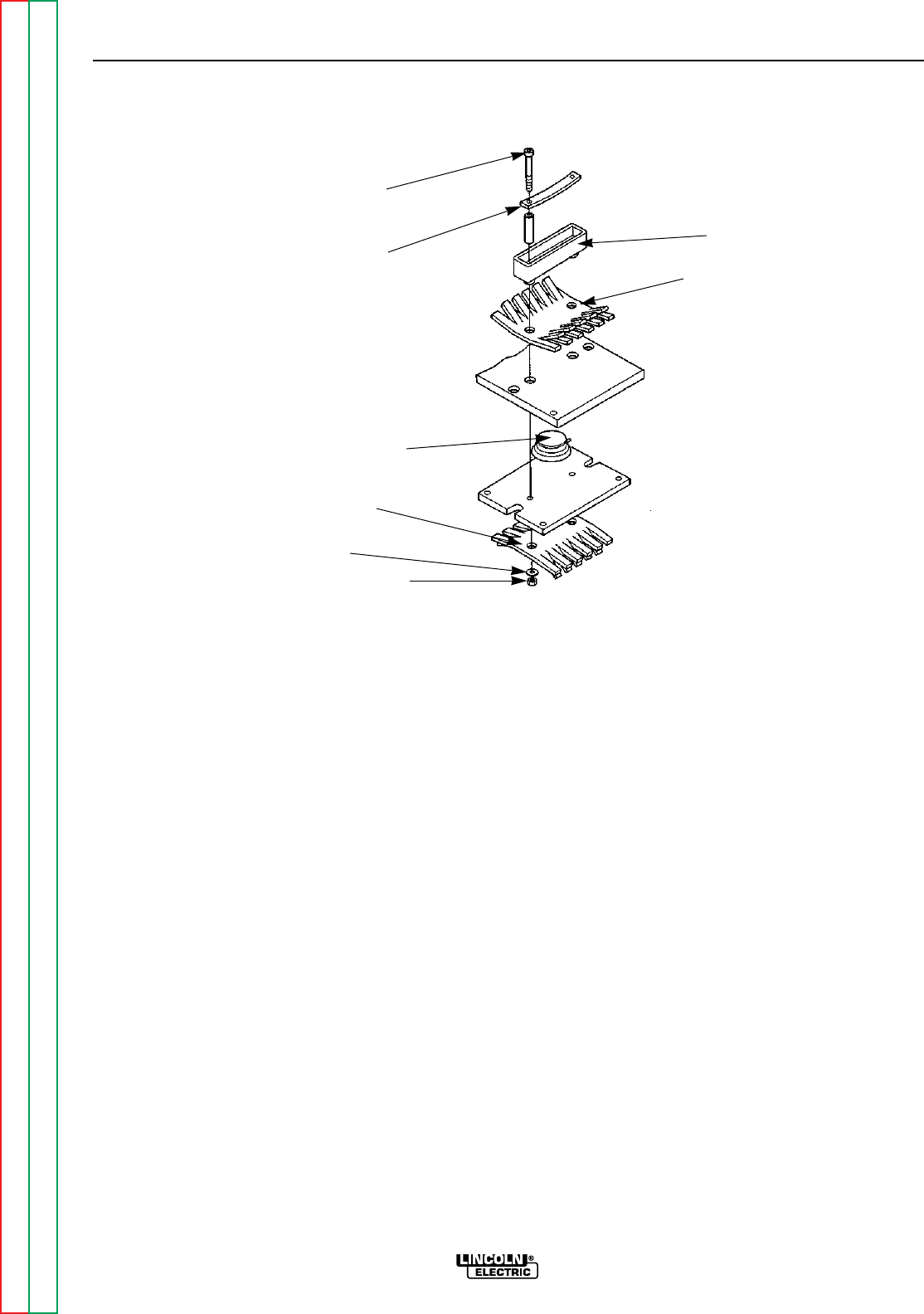
FIGURE F.29 – SCR CLAMP ASSEMBLY DETAILS – 1/2” WIDE SPRING
SCR REMOVAL AND AND REPLACEMENT (continued)
Plastic Housing
Cap Screw
Leaf Spring
Heat Sink
SCR
Heat Sink
Plain Washer
Clamp Nut