


F-26 F-26
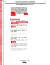
POWER BOARD TEST (continued)
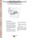
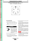
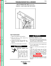
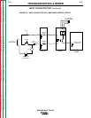
FIGURE F.4 - POWER BOARD TEST POINTS
TROUBLESHOOTING & REPAIR
TEST PROCEDURE
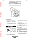
1. Remove input power to the machine.
2. With the 5/16" nut driver, remove the
screws and carefully lower the front control
panel.
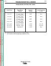
3. On the power board, locate the test points
that are called out in the following Power
Board Voltage Test Chart. See Figure F.4.
4. Connect the volt/ohmmeter to each set of
test points and compare your reading to the
expected reading from the chart.
ELECTRIC SHOCK can kill.
• With input power ON,
there are high voltages
inside the machine. Do
not reach into the machine
or touch any internal part
of the machine while
power is on.
• Apply power and press the start button.
• If the correct voltages are being applied
to the power board but NOT generated
by the power board, the power board
may be faulty.
• If the background voltages are NOT
being applied to the power board, the
control transformer, the background
rectifier, or the associated wiring may be
faulty.
5. After the tests are completed and the prob-
lem repaired, install the front control panel,
using the 5/16" nut driver.
SQUARE WAVE TIG 355
Return to Section TOC Return to Section TOC Return to Section TOC Return to Section TOC
Return to Master TOC Return to Master TOC Return to Master TOC Return to Master TOC
WARNING
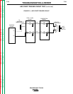
G2081-[ ]
SQUARE WAVE POWER
12 11 10 9 8 7
654321
109876
54321
J2
J4