


Return to Section TOC Return to Section TOC Return to Section TOC Return to Section TOC
Return to Master TOC Return to Master TOC Return to Master TOC Return to Master TOC
F-52 F-52
STATIC SCR TEST (continued)
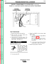
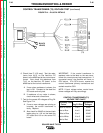
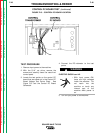
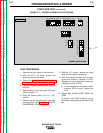
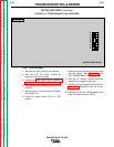
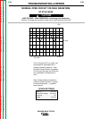
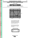
FIGURE F.17 – POWER PC BOARD PLUG LOCATIONS
TROUBLESHOOTING & REPAIR
TEST PROCEDURE
1. Remove the input power to the machine.
2. With the 5/16” nut driver, remove the
machine case top and sides.
3. Perform the Input Power Factor Capacitor
Voltage Check and Discharge procedure.
4. Remove the output welding cables from the
machine.
5. Remove plug J1 from the power PC board.
Refer to Figure F.17.
6. Place the polarity switch (S1) in a “DC”
position.
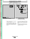
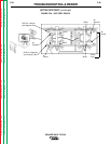
7. Remove the red insulating paint from heat
sink test points. See Figure F.18. DO NOT
DISASSEMBLE THE HEAT SINKS.
8. With the 1/2” wrench, remove the choke
lead from the negative plate (top).
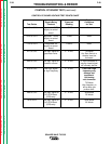
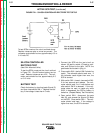
9. With the analog ohmmeter, test the resis-
tance from anode to cathode of SCR1.
Reverse the meter leads and check from
cathode to anode of SCR1.
A. If a low resistance is indicated in either
direction, SCR1 is faulty. Replace the
SCR.
10. Repeat Step 9 testing SCR2, SCR3, and
SCR4.
To further check SCR functions, use an
SCR tester and proceed to the Active SCR
test.
SQUARE WAVE TIG 355
J1
456321
1011
12
98
7
45321
3
2
1
910 8 7 6
8567
4123
12
3
4
SQUARE WAVE POWER
G2081-[ ]
J4
J2
J6
J5
J3
J1
14 13
11
12 10 9 8
45
6
7
32
1
6
5 4