


Return to Section TOC Return to Section TOC Return to Section TOC Return to Section TOC
Return to Master TOC Return to Master TOC Return to Master TOC Return to Master TOC
F-67 F-67
CONTROL PC BOARD REMOVAL AND REPLACEMENT (continued)
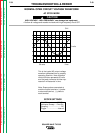
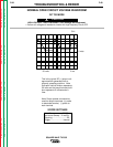
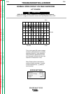
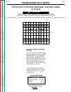
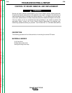
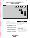
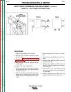
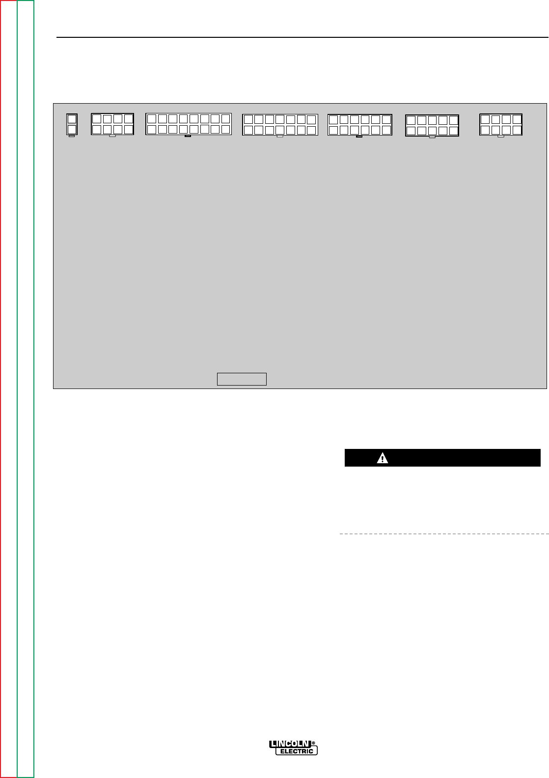
FIGURE F.22 - CONTROL PC BOARD
TROUBLESHOOTING & REPAIR
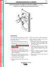
TEST PROCEDURE
Before starting the following procedure, refer
to the topic "PC Board Troubleshooting
Procedures" at the beginning of this section.
1. Remove input power to the machine.
2. With the 5/16" nut driver, remove the sheet
metal screws that hold the front control
panel in place. Carefully lower the panel.
3. Carefully remove the molex type plugs con-
nected to the control PC board. See Figure
F.22.
4. With the phillips head screw driver, remove
the mounting screws from the control PC
board.
5. Carefully remove the control PC board. Be
sure to observe static electricity cautions.
Be sure to follow the recommended static-free
methods for handling printed circuit boards.
Failure to do so can result in permanent dam-
age to the equipment.
6. Replace the old control PC board. Mount
the board with the mounting screws and
phillips head screw driver.
7. Carefully install the molex plugs that con-
nect to the control PC board.
8. Replace the front control panel and tighten
the sheet metal screws with the 5/16" nut
driver.
SQUARE WAVE TIG 355
CAUTION
G2081-[ ]
SQUARE WAVE 355 CONTROL
J8 J9 J10
J11
J12 J13 J14