


F-33 F-33
PILOT TRANSFORMER TEST (continued)
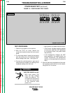
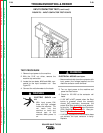
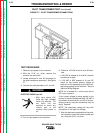
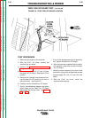
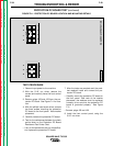
FIGURE F.7 - PILOT TRANSFORMER CONNECTIONS
TROUBLESHOOTING & REPAIR
TEST PROCEDURE
1. Remove input power to the machine.
2. With the 5/16" nut driver, remove the
machine top and sides.
3. Locate terminals X1 and X2 connected to
the pilot transformer secondary. See Figure
F.7.
4. Connect the volt/ohmmeter to X1 and X2.
ELECTRIC SHOCK can kill.
• With input power ON,
there are high voltages
inside the machine. Do
not reach into the
machine or touch any
internal part of the
machine while power is
on.
5. Turn on input power to the machine.
6. Check for 120 VAC at the X1 and X2 termi-
nals.
• If 120 VAC is present at X1 and X2, the pilot
transformer is good.
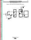
• If 120 VAC is NOT present at X1 and X2,
check for the correct primary voltage at
leads H1 to HX, depending on the input volt-
age being applied to the machine. See the
machine Wiring Diagram.
NOTE: H1 is located at L1 on the input side of
CR1 input contactor.
If the correct voltage is being applied to the
primary of the pilot transformer and 120 VAC is
not present at terminals X1 and X2 of the sec-
ondary winding, the pilot transformer may be
faulty. Replace.
NOTE: The secondary voltage will vary with
fluctuations in the input line voltage.
7. After the tests are completed and the prob-
lem repaired, install the machine sides and
top, using the 5/16" nut driver.
SQUARE WAVE TIG 355
Return to Section TOC Return to Section TOC Return to Section TOC Return to Section TOC
Return to Master TOC Return to Master TOC Return to Master TOC Return to Master TOC
WARNING
X1
X2