


Return to Section TOC Return to Section TOC Return to Section TOC Return to Section TOC
Return to Master TOC Return to Master TOC Return to Master TOC Return to Master TOC
F-39 F-39
PROTECTION PC BOARD TEST (continued)
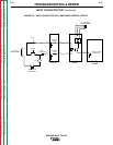
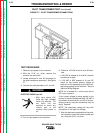
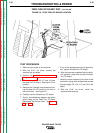
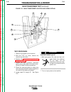
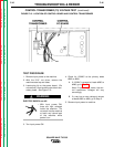
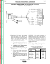
FIGURE F.11- PROTECTION PC BOARD LOCATION AND MOUNTING DETAILS
TROUBLESHOOTING & REPAIR
TEST PROCEDURE
1. Remove input power to the machine.
2. With the 5/16" nut driver, remove the
screws and carefully lower the front control
panel.
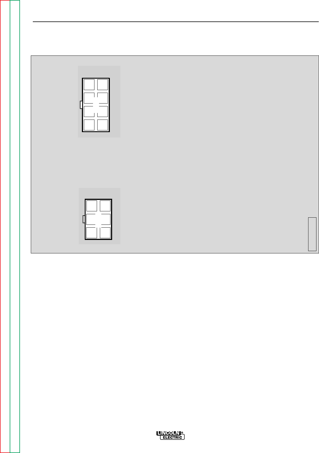
3. Remove plugs J22 and J23 from the pro-
tection PC board. See Figure F.11 for loca-
tion.
4. With the phillips head screw driver, remove
the three screws mounting the protection
PC board to the front panel. Note washer
placement.
5. Carefully remove the protection PC board.
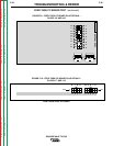
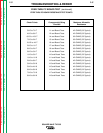
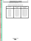
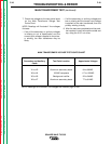
6. Test for the resistances between the check
points listed on the Protection PC Board
Resistance Test Points Chart.
• If any of the resistances are out of specifica-
tion, replace the protection PC board.
7. After the tests are complete and the prob-
lem repaired, install and connect the pro-
tection PC board.
• Carefully mount the protection PC board to
the front panel. Take note of the washer
placement; the washers must be replaced
correctly to be sure that the protection PC
board is grounded properly. See Figure
F.11.
• Connect plugs J22 and J23.
8. Install the front control panel, using the
5/16" nut driver.
SQUARE WAVE TIG 355
6
5 4
3 2
1
8
7 6
5
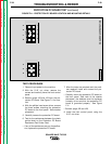
SQUARE WAVE PROTECTION
M16062-[ ]
4 3
21
J23
J22