


Return to Section TOC Return to Section TOC Return to Section TOC Return to Section TOC
Return to Master TOC Return to Master TOC Return to Master TOC Return to Master TOC
F-62 F-62
TROUBLESHOOTING & REPAIR
SQUARE WAVE TIG 355
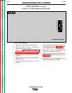
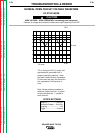
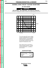
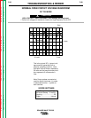
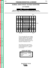
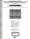
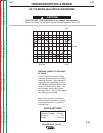
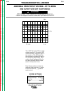
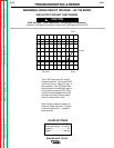
CH1
0 volts
2 ms
20 volts
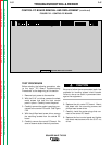
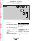
SCOPE SETTINGS
Volts/Div.....................20V/Div.
Horizontal Sweep.....2 ms/Div.
Coupling ............................DC
Trigger .........................Internal
MACHINE LOADED TO 350 AMPS
AT 34VDC
This is a typical DC (+) output voltage
waveform generated from a properly
operating machine. Note that each
vertical division represents 20 volts
and that each horizontal division rep-
resents 2 milliseconds in time. The
machine was loaded with a resis-
tance grid bank. The TIG 355 display
read 350 amps at 34 VDC.
Note: Scope probes connected at
machine output terminals: (+) probe
to electrode terminal, (-) probe to
work terminal.
TYPICAL OUTPUT VOLTAGE WAVEFORM – MACHINE LOADED
DC TIG MODE
HIGH VOLTAGE / HIGH FREQUENCY can damage test equipment.
• Perform all voltage and waveform checks with high frequency circuit OFF.
CAUTION