


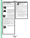
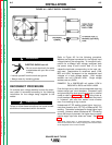
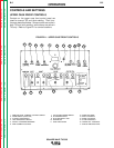

The Square Wave TIG 355 should be permanently
wired into the power system. Plugs or connectors are
not recommended.
INSTALLATION
A-6 A-6
SQUARE WAVE TIG 355
Return to Section TOC Return to Section TOC Return to Section TOC Return to Section TOC
Return to Master TOC Return to Master TOC Return to Master TOC Return to Master TOC
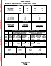
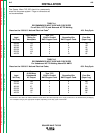
TABLE A.1
RECOMMENDED INPUT WIRE AND FUSE SIZES
For all Stick, DC TIG, and Balanced AC TIG Welding
Based on the 1990 U.S. National Electrical Code
(2)
40% Duty Cycle
Input Ampere Type 75°C
Input Rating on Wire in Conduit Grounding Wire Fuse Size
Volt/Freq. Nameplate AWG Copper Cond. AWG Copper Cond. (Super Lag)
208/60 110 4 6 150
230/60 100 6 6 125
460/60 50 8 10 60
200/50 115 4 6 150
220/50 104 4 6 125
440/50 52 8 10 60
TABLE A.2
RECOMMENDED INPUT WIRE AND FUSE SIZES
For Unbalanced AC TIG Welding Above 230 AMPS
Based on the 1990 U.S. National Electrical Code
(2)
60% Duty Cycle
Input Amperes
at 300 Amp Type 75°C
Input Unbalanced Wire in Conduit Grounding Wire Fuse Size
Volt/Freq. AC Output AWG Copper Cond. AWG Copper Cond. (Super Lag)
208/60 148 2 6 200
230/60 134 2 6 175
460/60 67 6 8 80
200/50 154 1 6 200
220/50 140 2 6 200
440/50 70 6 8 90
(2)
Article 630 of the 1990 U.S. National Electrical Code allows the rated ampacity of the supply conductors to be determined by multiplying
the nameplate rating by the appropriate multiplier, depending on the duty cycle of the welder.