


F-23 F-23
ARC START TRIGGER CIRCUIT TEST (continued)
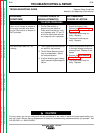
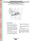
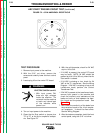
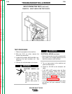
FIGURE F.2 – 6-PIN AMPHENOL RECEPTACLE
TROUBLESHOOTING & REPAIR
TEST PROCEDURE
1. Remove input power to the machine.
2. With the 5/16" nut driver, remove the
screws and carefully lower the front control
panel.
3. Locate plug J9 on the control PC board.
ELECTRIC SHOCK can kill.
• With input power ON,
there are high voltages
inside the machine. Do
not reach into the machine
or touch any internal part
of the machine while
power is on.
4. Turn on input power to the machine.
5. Close the Arc Start switch or jumper pins
"D" to "E" at the 6-pin amphenol recepta-
cle. See Figure F.2.
6. With the volt/ohmmeter, check for 24 VAC
at pins 1J9 to 3J9.
• If 24 VAC is present, the control PC board
may be faulty. NOTE: 24 VAC should be
present at pins 1J9 to 3J9 only when the Arc
Start switch is closed.
• If 24 VAC is missing or low, check for 24
VAC at the T5 transformer. See the Wiring
Diagram. If 24 VAC is missing or low at the
transformer leads, perform the Control
Transformer Test.
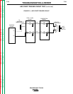
• If 24 VAC is present at the transformer leads,
remove input power to the machine and
check the continuity and resistance of the
leads and coils on and between the feed-
thru board and the protection board. See
Figure F.3.
7. Also check the continuity of the leads from
the protection board to the 14-pin amphe-
nol receptacle. It should be zero ohms.
See the Wiring Diagram.
8. After the tests are complete, install the front
control panel, using the 5/16" nut driver.
SQUARE WAVE TIG 355
Return to Section TOC Return to Section TOC Return to Section TOC Return to Section TOC
Return to Master TOC Return to Master TOC Return to Master TOC Return to Master TOC
WARNING
F
C
D
E
A
B