


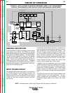

OUTPUT RECTIFICATION AND
FEEDBACK CONTROL
The AC output from the main transformer secondary is
rectified and controlled through the SCR bridge.
Output current is sensed at the shunt as a low voltage
signal and fed back to the control board. The control
board compares the commands of the control panels,
panel switches, and/or remote control with the shunt
feedback signal and electrode sense lead. The appro-
priate SCR gate firing commands are created by the
control board and sent to the power board where the
gate firing pulses are generated and applied through
the snubber board to the SCR bridge. The control
board controls the firing of the SCRs, which controls
the output of the machine. See SCR Operation. The
control board also powers and commands the display
board and the status board.
The electrode sense, the remote control and the trig-
ger signals are applied through the feed – thru board
to the control board.
THEORY OF OPERATION
E-3 E-3
SQUARE WAVE TIG 355
Return to Section TOC Return to Section TOC Return to Section TOC Return to Section TOC
Return to Master TOC Return to Master TOC Return to Master TOC Return to Master TOC
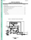
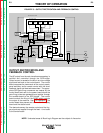
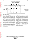
FIGURE E.3 – OUTPUT RECTIFICATION AND FEEDBACK CONTROL
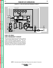
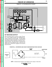
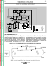
NOTE: Unshaded areas of Block Logic Diagram are the subject of discussion.
HIGH VOLTAGE
TRANSFORMER
CIRCUIT
REMOTE
RECEPTACLE
GAS/WATER
SOLENOIDS
FANS
115VAC
RECEPTACLE
INPUT
CONTACTOR
R
E
C
O
N
N
E
C
T
POWER
FACTOR
CAPACITORS
FEED - THRU
BOARD
CONTROL
BOARD
POWER
BOARD
SNUBBER
BOARD
MAIN
TRANSFORMER
AC
AC
DC-
DC+
POLARITY
SWITCH
SHUNT
C
H
O
K
E
BY-PASS
BOARDS
WORK
ELECTRODE
HI-FREQ
TRANSFORMER
PILOT
TRANSFORMER
START/
STOP
PANEL
SWITCHES
UPPER
CONTROL
PANEL
LOWER
CONTROL
PANEL
DISPLAY
BOARD
STATUS
BOARD
ELECTRODE SENSE
HIGH FREQUENCY SPARK
115VAC
INTERLOCK
HI-FREQ AND GAS/WATER
115VAC -
115VAC
CONTROL TRANSFORMER
INTERLOCK
ELECTRODE
SENSE
REMOTE
COMMANDS
GATE COMMANDS
HI-FREQ/
WATER/GAS
COMMANDS
INTERLOCK
115VAC
SCR
TRIGGER
15VDC
115VAC