


Return to Section TOC Return to Section TOC Return to Section TOC Return to Section TOC
Return to Master TOC Return to Master TOC Return to Master TOC Return to Master TOC
F-82 F-82
TROUBLESHOOTING & REPAIR
SQUARE WAVE TIG 355
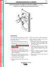
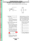
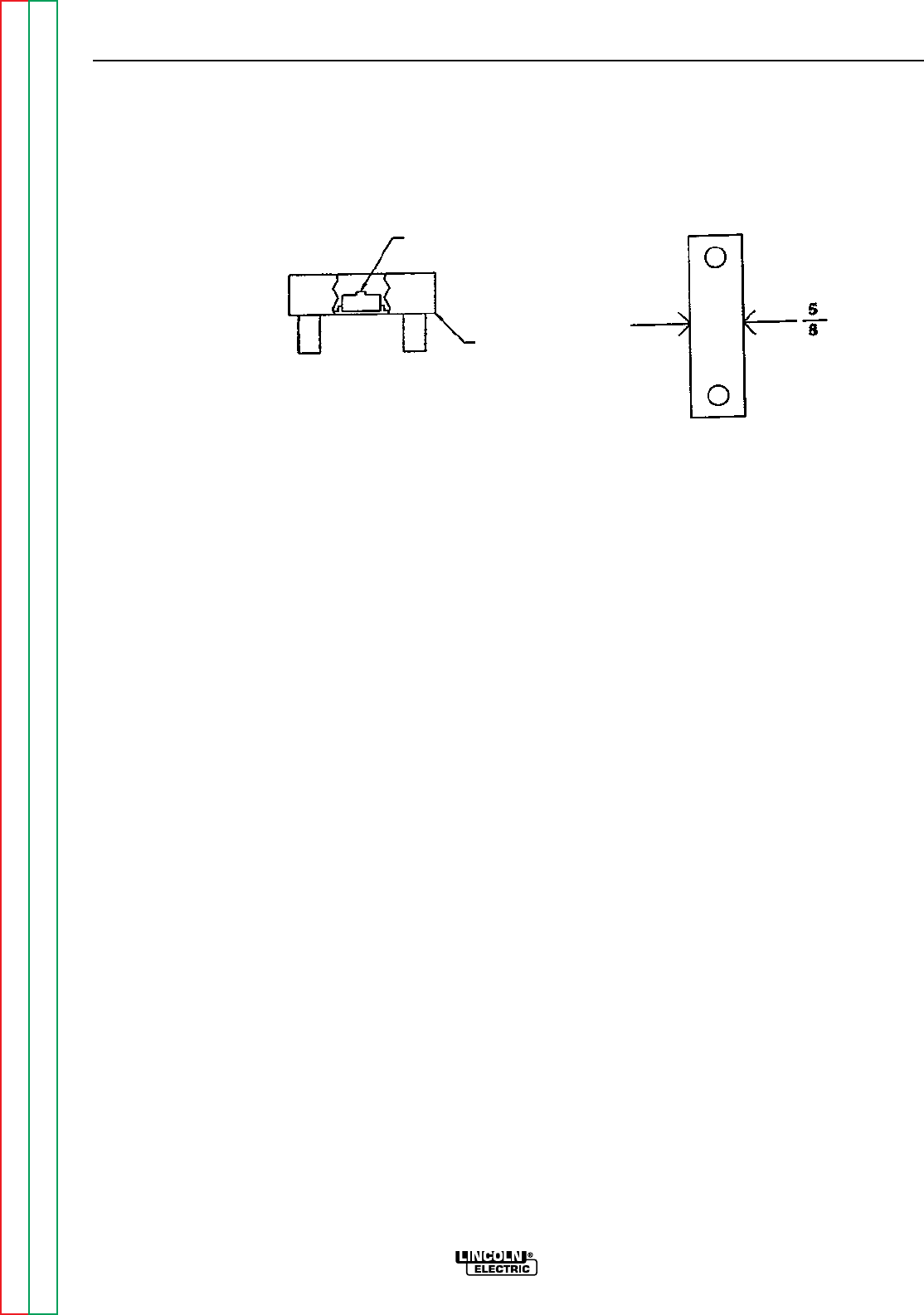
B. PROCEDURE FOR THE 5/8 INCH
WIDE SPRING:
1) Place a piece of sleeving around
each cap screw.
2) Insert the cap screws through the
leaf spring. The leaf spring is flat
so the orientation of the leaf spring
does not matter.
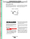
3) Place the steel pressure pad in the
housing with the 1/8” wide standoff
facing up. See Figure 30.
4) Insert the cap screws and leaf
spring into the plastic housing. Be
sure that the steel pressure pad
remains in position. Pressing on
the cap screw heads should pro-
duce a rocking action of the spring
in its housing.
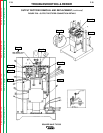
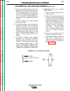
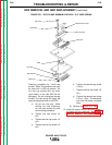
5) Insert the clamp assembly through
the heat sinks. Install the nuts.
Tighten the clamp nuts equally on
the cap screws until finger tight.
Be sure that the leaf spring is not
cocked in the housing. See Figure
31.
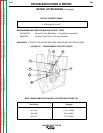
6) Re-inspect the SCR for proper
seating.
7) Clamp the cap screws. Use the
procedure for 1/4-28 cap screws or
1/4-20 cap screws, depending on
which you have.
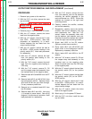
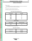
Clamping procedure for 1/4-28 cap
screws. Note: This procedure can only
be used with 1/4-28 cap screws. Do
not use cap screws with any other type
thread, or the new SCR will be dam-
aged. Do not overtighten the cap
screws. The leaf spring will apply the
required clamping force to the SCR.
a. Do not turn the nuts. While
holding the nuts stationary,
turn the cap screws only with
the following procedure.
b. Tighten first cap screw 1/4
turn.
c. Tighten second cap screw 1/2
turn.
d. Tighten first cap screw 1/2
turn.
e. Tighten second cap screw 1/2
turn.
f. Tighten first cap screw 1/2
turn.
g. Tighten second cap screw 1/4
turn. Stop. The assembly now
has the proper clamping force.
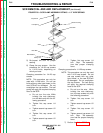
FIGURE F.30 – HOUSING AND PRESSURE PAD FOR 5/8” WIDE LEAF SPRING
SCR REMOVAL AND AND REPLACEMENT (continued)
Steel Pressure Pad
Housing