


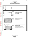

TIG WELDING SEQUENCE OF
OPERATION (2-STEP MODE)
Do not leave stick electrode welding cable connected.
It will be electrically “hot” when TIG welding.
1. Connect an Amptrol or Arc Start switch to the
Remote Receptacle.
2. Turn the welder, water supply (if equipped) and
gas supply on. The pilot light on the front panel
indicates when the power is on.
3. Select REMOTE or LOCAL current control
(REMOTE requires an Amptrol).
Select TIG mode.
Select CONTINUOUS or START high frequency.
Select AC or DC- electrode polarity. See Table B.3
for recommended polarity settings.
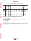
TABLE B.3
RECOMMENDED SETTINGS FOR TIG WELDING
Electrode High Frequency
Type of Welding Polarity Switch
Stainless Steel DC- Start
Aluminum and
Magnesium AC Continuous
Other Metals DC- Start
4. Preset the maximum current with the Current con-
trol and the Ammeter.
5. (Arc Force control has no effect in TIG mode.)
6. If in AC, set AC Wave Balance control. (See CON-
TROLS AND SETTINGS, item 8, “AC Wave
Balance.” This control has no effect in DC.)
7. Set Afterflow time.
8. Set Function Panel controls as needed. (See
CONTROLS AND SETTINGS.)
9. Press the Arc Start switch or Amptrol and set the
gas flowmeter. The welder is now ready for weld-
ing.
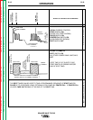
10. Position the tungsten electrode at the start of the
weld at a 65° to 75° angle with the horizontal so
that the electrode is approximately 1/8” (3.2 mm)
above the workpiece. Press the Arc Start switch
or operate the Amptrol. This opens the gas and
water valves to automatically purge air from the
hose and torch. After a time determined by the
Preflow control setting, the high frequency
becomes available to strike the arc.
11. Hold the Arc Start Switch down or operate the
Amptrol until the weld is completed. Release the
Arc Start switch or the Amptrol to stop the arc.
When the Afterflow timer completes the cycle, the
gas and water valves close. To make another
weld, repeat steps 10 and 11.
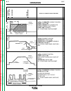
TIG WELDING SEQUENCE OF
OPERATION (4-STEP MODE)
Do not leave stick electrode welding cable connected.
It will be electrically “hot” when TIG welding.
1. Connect an Arc Start switch to the Remote
Receptacle.
2. Turn the welder, water supply (if so equipped) and
gas supply on. The pilot light on the front panel
indicates when the power is on.
3. Select LOCAL current control. Select TIG mode.
Select CONTINUOUS or START high frequency.
Select AC or DC- electrode polarity (See Table
B.3 for recommended polarity settings).
4. Preset the maximum current with the Peak
Current control and the Ammeter.
5. (Arc Force Control has no effect in TIG mode.)
6. If in AC, set AC Wave Balance control. (See CON-
TROLS AND SETTINGS, item 8, “AC Wave
Balance. This control has no effect in DC.)
7. Set Afterflow time.
8. Set Function Panel controls as needed. (See
CONTROLS AND SETTINGS, “Lower Case Front
Controls”)
9. Press the Arc Start switch and set the gas
flowmeter. The welder is now ready for welding.
10. Position the tungsten electrode at the start of the
weld at a 65° to 75° angle with the horizontal so
that the electrode is approximately 1/8” (4 mm)
above the workpiece. Press the Arc Start switch.
This opens the gas and water valves to automati-
cally purge air from the hose and torch. After a
time determined by the Preflow control setting,
the high frequency becomes available to strike the
arc.
OPERATION
B-20 B-20
SQUARE WAVE TIG 355
Return to Section TOC Return to Section TOC Return to Section TOC Return to Section TOC
Return to Master TOC Return to Master TOC Return to Master TOC Return to Master TOC
WARNING
WARNING