


Return to Section TOC Return to Section TOC Return to Section TOC Return to Section TOC
Return to Master TOC Return to Master TOC Return to Master TOC Return to Master TOC
THEORY OF OPERATION
E-6 E-6
SQUARE WAVE TIG 355
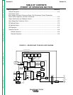
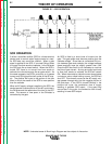
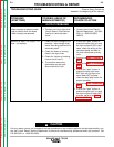
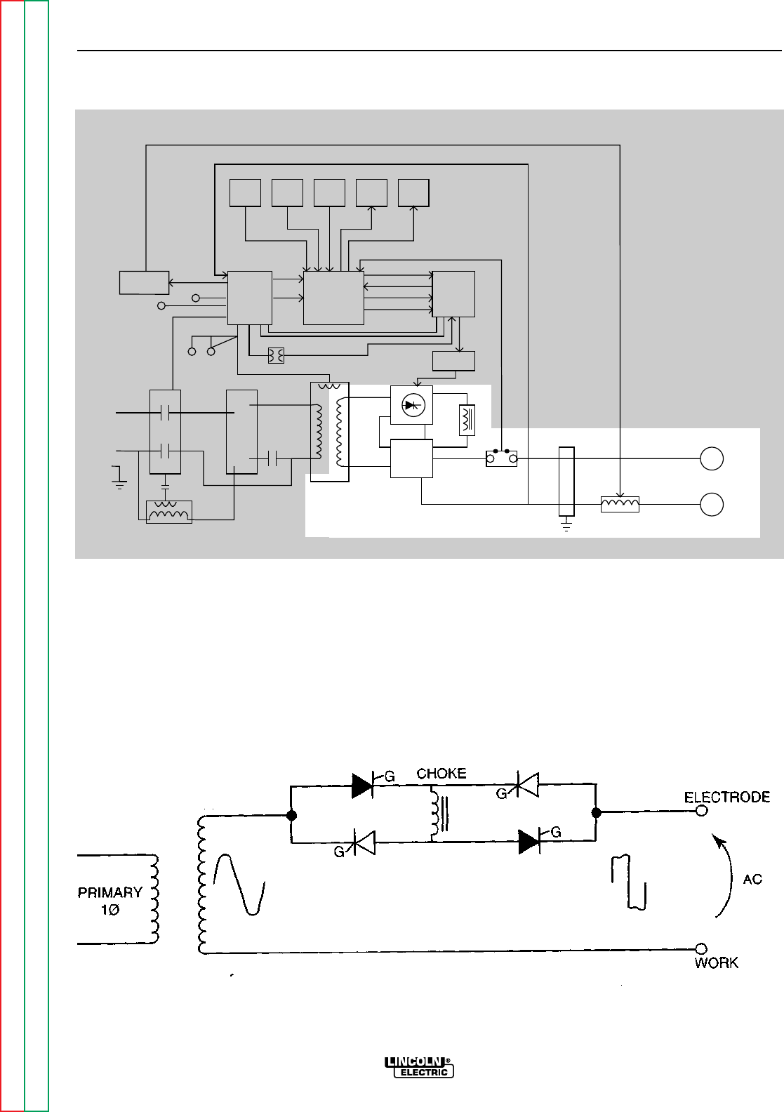
AC WELDING OUTPUT
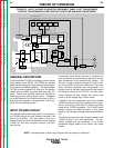
Rotating the polarity switch to the AC position
changes the welding power circuit. One lead (X2) of
the main transformer secondary is connected to the
machine output work terminal. The other secondary
lead (X1) is connected to one of the AC connections
on the SCR bridge. The electrode terminal is con-
nected to the other AC side of the bridge. The choke
is now electrically across the negative and positive
SCR bridge connections. With the ability of the choke
to store energy and the SCRs to turn on at the appro-
priate times, an AC square wave is developed and
applied to the output terminals.
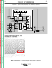
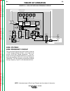
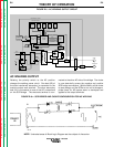
FIGURE E.6 – AC WELDING OUTPUT CIRCUIT
NOTE: Unshaded areas of Block Logic Diagram are the subject of discussion.
HIGH VOLTAGE
TRANSFORMER
CIRCUIT
REMOTE
RECEPTACLE
GAS/WATER
SOLENOIDS
FANS
115VAC
RECEPTACLE
INPUT
CONTACTOR
R
E
C
O
N
N
E
C
T
POWER
FACTOR
CAPACITORS
FEED - THRU
BOARD
CONTROL
BOARD
POWER
BOARD
SNUBBER
BOARD
MAIN
TRANSFORMER
AC
AC
DC-
DC+
POLARITY
SWITCH
SHUNT
C
H
O
K
E
BY-PASS
BOARDS
WORK
ELECTRODE
HI-FREQ
TRANSFORMER
PILOT
TRANSFORMER
START/
STOP
PANEL
SWITCHES
UPPER
CONTROL
PANEL
LOWER
CONTROL
PANEL
DISPLAY
BOARD
STATUS
BOARD
ELECTRODE SENSE
HIGH FREQUENCY SPARK
115VAC
INTERLOCK
HI-FREQ AND GAS/WATER
115VAC -
115VAC
CONTROL TRANSFORMER
INTERLOCK
ELECTRODE
SENSE
REMOTE
COMMANDS
GATE COMMANDS
HI-FREQ/
WATER/GAS
COMMANDS
INTERLOCK
115VAC
SCR
TRIGGER
15VDC
115VAC
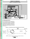
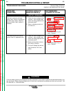
FIGURE E.6a – SCR BRIDGE AND CHOKE CONFIGURATION FOR AC WELDING
X1
X2