


Return to Section TOC Return to Section TOC Return to Section TOC Return to Section TOC
Return to Master TOC Return to Master TOC Return to Master TOC Return to Master TOC
F-72 F-72
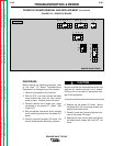
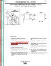
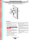
INPUT CONTACTOR REMOVAL AND REPLACEMENT (continued)
TROUBLESHOOTING & REPAIR
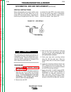
13. Replacement: Mount the contactor brack-
et assembly to the case back and attach it
with the 4 mounting screws. Use the
5/16" nut driver.
14. Attach leads #243 and #242 to the con-
tactor interlock located on the bottom of
the contactor.
15. Attach leads #243 and #244 to the con-
tactor coil tabs.
16. Attach small lead #246 to the L2 terminal.
17. Attach small lead H1 to the L1 terminal.
18. With the slot head screw driver, attach the
copper strap, the heavy lead, and the
small capacitors to the output side of the
contactor.
19. With the slot head screw driver, attach the
input leads to the L1 and L2 terminals on
the input contactor.
20. With the 5/16" nut driver, install the rear
access panel, case sides and top.
SQUARE WAVE TIG 355