


Return to Section TOC Return to Section TOC Return to Section TOC Return to Section TOC
Return to Master TOC Return to Master TOC Return to Master TOC Return to Master TOC
F-77 F-77
TROUBLESHOOTING & REPAIR
SQUARE WAVE TIG 355
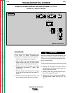
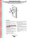
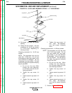
OUTPUT RECTIFIER REMOVAL AND REPLACEMENT (continued)
PROCEDURE
1. Remove input power to the machine.
2. With the 5/16" nut driver, remove the case
top and sides.
3. Perform the Input Power Factor Capacitor
Voltage Check.
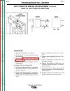
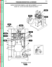
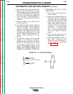
For Steps 4-27, refer to Figure F.26.
4. Remove plug J1 from the power PC board.
5. With the 1/2" wrench, remove the choke
lead from the negative plate.
6. With the 1/2" wrench, remove the X1 lead
from SCR1 - SCR4 junction. Note lead
placement for reassembly: X1 is sand-
wiched between the two leads from the
output rectifier bridge.
7. With the 1/2" wrench, remove the lead at
the SCR2 - SCR3 junction leading to the
polarity switch (S1). Note lead placement
for reassembly.
8. With the 1/2" wrench, remove the lead
from the positive plate leading to the
polarity switch (S1).
9. With the 7/16" wrench, remove the small
lead from the negative plate leading to
CR3 relay.
10. With the 7/16" wrench, remove D1, D2
and the copper strap lead assembly from
the insulated stud on the negative plate.
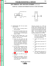
11. Remove leads #215 and #264 from the R7
resistor.
12. Remove leads #213 and #214/214A from
the background rectifier. Separate leads
#214 and #214A and pull them through.
Cut any necessary cable ties.
13. Remove (cut or unsolder) lead #212 from
the R3 resistor.
14. Remove leads #210 and #211 from plug
J1 (Located at power board. See wiring
diagram). Use a molex pin extractor. Note
lead placement for reassembly.
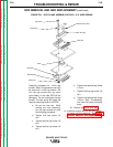
15. With the 7/16" wrench, remove the four
nuts, lock washers, and two flat washers
mounting the rectifier assembly to the
main transformer iron. NOTE: The two flat
washers are located on the right hand
mounting screws.
16. Carefully remove the rectifier, snubber,
and torriod assembly.
17. Reassembly: carefully mount the rectifier,
snubber, and torriod assembly onto the
main transformer iron. With the 7/16"
wrench, fasten the assembly down with
the flat washers, lock washers, and nuts.
Note that the two flat washers are located
on the the right hand mounting screws.
18. Attach lead #212 to the R3 resistor.
(Splice or solder the connection.)
19. Route leads #213 and #214/214A and
attach them to the background rectifier.
Replace any necessary cable ties.
20. Attach leads #215 and #264 to the R7
resistor.
21. With the 7/16" wrench, attach D1, D2 and
the copper strap lead assembly to the
insulated stud on the negative plate.
Attach the small lead from the CR3 relay
to the negative plate.
22. With the 1/2" wrench, attach the lead from
the polarity switch (S1) to the positive
plate.
23. With the 1/2" wrench, attach the lead from
the polarity switch (S1) at the SCR2 -
SCR3 junction.
24. With the 1/2" wrench, attach the X1 lead
to the SCR1 - SCR4 junction. X1 is sand-
wiched between the two leads from the
output rectifier bridge.
25. With the 1/2" wrench, attach the choke
lead to the negative plate.
26. Attach plug J1 to the power PC board.
27. With the 5/16" nut driver, install the case
top and sides.