


Return to Section TOC Return to Section TOC Return to Section TOC Return to Section TOC
Return to Master TOC Return to Master TOC Return to Master TOC Return to Master TOC
F-50 F-50
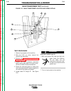
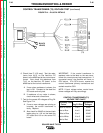
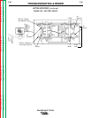
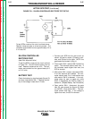
CONTROL PC BOARD TEST (continued)
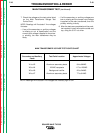
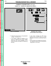
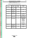
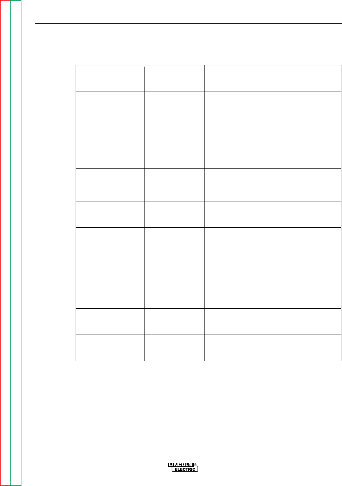
CONTROL PC BOARD VOLTAGE TEST POINTS CHART
TROUBLESHOOTING & REPAIR
SQUARE WAVE TIG 355
Special
Signals Being Expected Conditions
Test Points Checked Reading for Test
3J13 to 5J13 Regulated +15VDC +15VDC None
supply to control
board
4J13 to 5J13 Regulated -15VDC -15VDC None
supply to control
board
1J13 to 2J13 Unregulated DC +12VDC None
supply to control
board
R11 to 5J13 Low logic signal for 0 - 2 VDC TIG Mode
gas/water valve Arc Start Switch or
Amptrol must be
activated
R32 to 5J13 Low logic signal for 0 - 2 VDC If input contactor is
interlock control staying closed signal
will normally be low.
R13 to 5J13 Low logic signal 0 - 2 VDC CAUTION: High
for high frequency frequency may
damage test
equipment.
Use analog
volt/ohmmeter
TIG Mode
High frequency is
active after gas
preflow time.
R66 to 5J13 Low logic signal for 0 - 2 VDC StickMode
DC OCV Boost DC Mode
(CR3) relay
R8 to 5J13 Low logic signal for 0 - 2 VDC Stick Mode
AC OCV Boost AC Mode
(CR2) relay