


Return to Section TOC Return to Section TOC Return to Section TOC Return to Section TOC
Return to Master TOC Return to Master TOC Return to Master TOC Return to Master TOC
SQUARE WAVE TIG 355
F-21 F-21
INPUT POWER FACTOR CAPACITOR VOLTAGE CHECK
AND DISCHARGE PROCEDURE (continued)
TROUBLESHOOTING & REPAIR
TEST PROCEDURE
1. Remove input power to the machine.
2. With the 5/16" nut driver, remove the sheet
metal screws that hold the right case side
in place. Remove the right case side.
3. With the volt/ohmmeter, carefully check the
voltage across the input power factor
capacitors. When input power is removed,
the voltage across each capacitor should
be zero. (Normally, the capacitors dis-
charge through the primary winding in the
main transformer.)
4. If capacitor voltage is zero, you may begin
working on the Square Wave TIG 355.
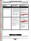
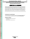
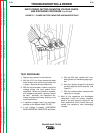
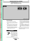
5. If any voltage is present, DISCHARGE
EACH INDIVIDUAL CAPACITOR as follows:
a. Grip the 500 ohm resistor with insu-
lated gloves and insulated gripping pli-
ers.
b. Hold the resistor across the terminals
on each capacitor for 20 seconds. See
Figure F.1.
c. With the volt/ohmmeter, recheck each
capacitor for voltage.
6. After all the capacitors are discharged
completely, check for broken capacitor
leads or an open primary winding on the
main transformer, which would have pre-
vented the capacitors from discharging
normally.
FIGURE F.1 – POWER FACTOR CAPACITOR DISCHARGE DETAILS