


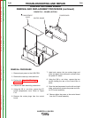


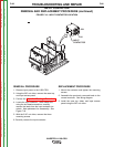


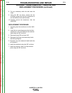


TRANSFORMER #2
3/8” MOUNTING
SCREWS (2)
P51
P52
P50
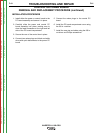
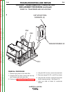
TRANSFORMER #2
3/8” MOUNTING
SCREWS (2)
P51
P52
P50
FIGURE F.19 – TRANSFORMER AND PLUG LOCATIONS
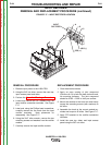
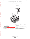
AUXILIARY TRANSFORMER NO. 2 REMOVAL AND
REPLACEMENT PROCEDURE (continued)
REMOVAL PROCEDURE
1. Remove input power to the V450-PRO.
2. Using the 3/8” nut driver, remove the case top,
input access panel and case sides.
3. Perform the Capacitor Discharge Procedure.
4. Using the 3/8” nut driver, remove the case back.
5. Disconnect plugs P50, P51, and P52 and clean.
6. Using the 3/8” nut driver, remove the two trans-
former mounting screws. See Figure F19.
7. Label and clean all leads for transformer
removal.
TROUBLESHOOTING AND REPAIR
F-68 F-68
INVERTEC® V450-PRO
Return to Section TOC Return to Section TOC Return to Section TOC Return to Section TOC
Return to Master TOC Return to Master TOC Return to Master TOC Return to Master TOC