


OUTPUT PROBLEMS
Observe Safety Guidelines detailed in the beginning of this manual.
PROBLEMS
(SYMPTOMS)
POSSIBLE AREAS OF
MISADJUSTMENT(S)
RECOMMENDED
COURSE OF ACTION
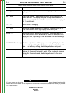
If for any reason you do not understand the test procedures or are unable to perform the tests/repairs safely,
contact the Lincoln Electric Service Department for technical troubleshooting assistance before you proceed.
Call 1-888-935-3877.
CAUTION
TROUBLESHOOTING AND REPAIR
F-6 F-6
INVERTEC® V450-PRO
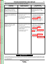
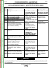
The INVERTEC® V450-PRO
does not have welding output.
The main input contactor (CR1) is
not activating.
NOTE: This problem will
normally be accompanied
by an error code.
The Diagnostic Utility is also
available on the Service
Navigator.
1. The input voltage may be too
high or too low or reconnect
panel may be incorrectly
connected
2. May be a thermal shutdown.
Check to see if the Thermal
LED is ON
3. The primary current limit has
been exceeded (CR1 drops out
when the output is initiated).
4. The power source (upper
section) has failed. If nothing
is evident from a visual
inspection, perform tests as
shown.
NOTE: Error codes as indicated
by LED 9 and 10 on the
Control Board.
1. Make certain that the input
voltage is proper, according
to the Rating Plate located on
the rear of the machine. See
Installation Section of this
manual.
2. See “Thermal LED is ON” in
this section.
3. Possible short in output
circuit. Turn machine off.
Remove all leads from the
output of the machine.
4. Perform the Input Contactor
Test.
5. Perform the Input Board
Test.
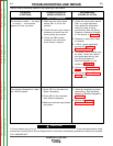
6. Perform the Auxiliary
Transformer test for T-1
7. Preform the Input Rectifier
test.
8. Perform the IGBT Switch
Board Test.
9. Perform the Power Board
Test.
10. Perform the Control Board
Check. The Control Board
may be faulty.
Return to Section TOC Return to Section TOC Return to Section TOC Return to Section TOC
Return to Master TOC Return to Master TOC Return to Master TOC Return to Master TOC