


THERMOSTAT TEST – THERMAL PROTECTION (continued)
TROUBLESHOOTING AND REPAIR
F-48 F-48
INVERTEC® V450-PRO
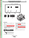
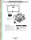
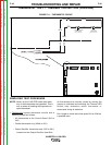
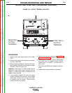
FIGURE F.11 – THERMOSTAT CIRCUIT
NOTE: Never run the V-450 PRO under load when
any of the thermostats are bypassed. This is
only a means of isolating the inoperative or
open thermostat.
1. Temporarily
bypass thermostat circuits with a
shorting jumper as follows:
• All thermostats at the Control Board (2J5 to
3J5)
• Choke thermostat only (224A to 291)
• Output Rectifier thermostat only (220 to 291)
Located on the Output Rectifier Heat Sink
All thermostats are normally closed so moving the
jumper as indicated and watching the Thermal LED
should help determine which thermostat or
associated wiring is defective.
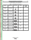
Don’t forget to check the incline splice 224 to 224A as
a possible open.
J5-2
J5-3
224
220
220
224
224A
291
224A
O
UTPUT RECTIFIER
THERMOSTAT
(BOLTED CONNECTION)
CHOKE
THERMOSTAT
(CONNECTED W/EPOXY)
J5-2
J5-3
224
220
220
224
224A
291
224A
O
UTPUT RECTIFIER
THERMOSTAT
(BOLTED CONNECTION)
CHOKE
THERMOSTAT
(CONNECTED W/EPOXY)
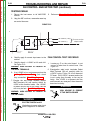
SIMPLIFIED TEST PROCEDURE
LED 6
J5
Thermostat
LED 6
J5
Thermostat
Return to Section TOC Return to Section TOC Return to Section TOC Return to Section TOC
Return to Master TOC Return to Master TOC Return to Master TOC Return to Master TOC