


INSTALLATION
A-7 A-7
INVERTEC® V450-PRO
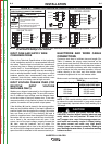
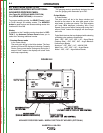
LN-742 Connection Instructions
• Turn the Invertec® power switch "off"
• A K1819-1 Input cable assembly is required to con-
nect the LN-742 to the Invertec®.
• Connect the control cable from the LN-742 to the
14-pin MS-style connector.
• Connect the electrode cable to the output terminal
of the polarity required by electrode. Connect the
work lead to the other terminal.
• Set the meter polarity switch on the front of the
Invertec® to coincide with wire feeder polarity used.
The wire feeder will now display the welding volt-
age.
• If a remote control such as K857 is to be used with the
LN-742, the remote can be connected directly to the 6-pin
MS-style connector on the front of the Invertec® or use a
K864 adapter to connect the LN-742 and the remote to
the 14-pin MS-style connector.
Cobramatic Connection Instructions
• Turn the Invertec® power switch "off"
• Connect the control cable from the Cobramatic to
the 14-pin MS-style connector.
• Connect the electrode cable to the output terminal
of the polarity required by electrode. Connect the
work lead to the other terminal.
• Set the meter polarity switch on the front of the
Invertec® to coincide with wire feeder polarity used.
• If a remote control such as K857 is to be used with
the Cobramatic, the remote can be connected
directly to the 6-pin MS-style connector on the front
of the Invertec® or use a K864 adapter to connect
the cobramatic and the remote to the 14-pin MS-
style connector.
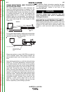
TIG Module K930-2
The TIG Module connects to the Factory and Advanced
Process
V450-Pro versions with a K936-1 (9-14 pin)
control cable. Connect the K936-1 to the 14-Pin MS-
style connector.
General Instructions for Connection of Wire
Feeders to V450-Pro
Wire feeders other than those listed above may be
used provided that the auxiliary power supply rating of
the V450-Pro is not exceeded and the V450-PRO out-
put is not actively controlled by the wire feeder. (Like
an LN-9). K867 universal adapter plug is required. See
connection diagram S24985 in Operator Manual.
REMOTE CONTROL OF INVERTEC®
Remote Control K857, Hand Amptrol K963 and Foot
Amptrol K870 may be used.
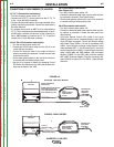
PARALLEL OPERATION
The V450-Pro are operable in parallel in CC mode. For
best results, the currents of each machine should be
reasonably equally balanced. As an example, with two
machines set up in parallel for a 800 amps procedure,
each machine should be set to deliver approximately
400 amps, not 450 amps from one and 350 amps from
the other. This will minimize nuisance shutdown condi-
tions. In general, more than two machines in parallel
will not be effective due to the voltage requirements of
procedures in that power range.
To set machine outputs, start with output control pots
and arc control pots in identical positions. Use the out-
put control pots to balance the currents and maintain
the desired current. The arc control pots should be
kept identical on the two machines.
Return to Section TOC Return to Section TOC Return to Section TOC Return to Section TOC
Return to Master TOC Return to Master TOC Return to Master TOC Return to Master TOC