


CAPACITOR
TERMINALS
RESISTOR
CAPACITOR
TERMINALS
RESISTOR
CAPACITOR
TERMINALS
RESISTOR
CAPACITOR
TERMINALS
RESISTOR
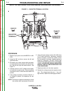
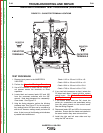
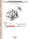
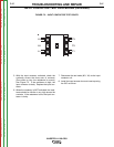
FIGURE F.2 - CAPACITOR TERMINAL LOCATIONS
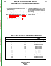
MAIN SWITCH BOARD TEST PROCEDURE (continued)
TEST PROCEDURE
1. Remove input power to the INVERTEC®
V450-PRO.
2. Perform the Capacitor Discharge Procedure.
3. Use a DC voltmeter to check that the voltage is
not present across the terminals on three
capacitors.
4. Locate label and remove leads 19C and 19D
from the reconnect switches with the 3/8”
wrench. Note lead placement for reassembly.
Clear leads. See Figure F.2.
5. Using the Analog ohmmeter, perform the following
resistance tests. See Figure F.2 for the test points.
Any readings below 100 ohms can be considered a
short circuit. However, readings usually are below 30
ohms. A short on any of the following points indicates
a possible failed switch board.
Check 11/12 to -20 and 11/12 to +19
Check 15/16 to -20 and 15/16 to +19
Check 13/14 to -20 and +19 to 13/14
Check 17/18 to -20 and +19 to 17/18
6. If any test fails (measures a short) isolate the
PC board and retest, if board still fails, replace
switch board. See Switch Board Removal
and Replacement.
7. If the switch board tests are OK, check the
molex pin connections and associated wiring
from the switch boards to the control board.
See the Wiring Diagram.
8. Reconnect leads 19C and 19D to the reconnect
switches. Ensure that the leads are installed in
the same location they were removed from.
9. Install the right and left case sides and top
using the 3/8” nut driver.
TROUBLESHOOTING AND REPAIR
F-20 F-20
INVERTEC® V450-PRO
Return to Section TOC Return to Section TOC Return to Section TOC Return to Section TOC
Return to Master TOC Return to Master TOC Return to Master TOC Return to Master TOC