


INPUT CONTACTOR TEST PROCEDURE (continued)
PROCEDURE
1. Remove input power to the INVERTEC®
V450-PRO.
2. Using the 3/8” nut driver, remove the input
access panel and case top.
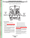
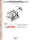
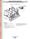
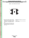
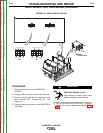
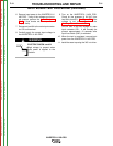
3. Locate, mark, and remove the two leads (601,
X4) that are connected to the input contactor
coil. See Figure F.4.
4. Using the external 24 VAC supply, apply 24
VAC to the terminals of the input contactor coil.
If the contactor does NOT activate, the input
contactor is faulty. Replace.
TROUBLESHOOTING AND REPAIR
F-26 F-26
INVERTEC® V450-PRO
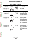
INPUT
C
ONTACTOR
601
X4
INPUT
C
ONTACTOR
601
X4
FIGURE F.4 – INPUT CONTACTOR COIL
Return to Section TOC Return to Section TOC Return to Section TOC Return to Section TOC
Return to Master TOC Return to Master TOC Return to Master TOC Return to Master TOC