


INSTALLATION
A-6 A-6
INVERTEC® V450-PRO
CONNECTIONS OF WIRE FEEDERS TO V450-PRO
LF-72, 74 Connection Instructions
• Turn the Invertec® power switch "off".
• Connect the K1797-[ ] control cable from the LF-72, 74
to the 14-pin MS-style connector.
• Connect the electrode cable to the output terminal of the
polarity required by electrode. Connect the work lead to
the other terminal.
• If a remote control such as K857 is to be used with the
LF-72, 74 the remote can be connected directly to the 6-
pin MS-style connector on the front of the Invertec® or
use a K864 adapter to connect the LF-72, 74 and the
remote to the 14-pin MS-style connector.
LN-10, DH-10 Connection Instructions
• Turn the Invertec® power switch "off"
• Connect the K1505 control cable from the LN-10 to the
14-pin MS-style connector.
• Connect the electrode cable to the output terminal of
polarity required by the electrode. Connect the work lead
to the other terminal.
• Set the meter polarity switch on the front of the Invertec®
to coincide with wire feeder polarity used.
• See the LN-10 manual for details on accessing Control
DIP Switch. Dip Switches for the V350 and the same set-
tings may be used for the V450.
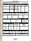
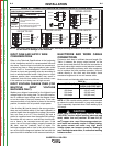
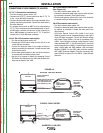
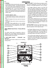
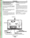
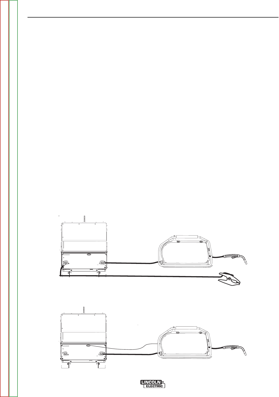
LN-15 Connection Instructions
(See Figure A.4)
• Turn the Invertec® power switch "off".
• Connect the electrode cable to the output terminal of polar-
ity required by electrode. (See Figures below)
• Set the meter polarity switch on the front of the Invertec®
to coincide with wire feeder polarity used.
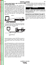
LN-25 Connection Instructions
• Turn the Invertec® power switch "off".
• Connect the electrode cable to the output terminal of polar-
ity required by electrode. Connect the work lead to the
other terminal.
• LN-25 with Remote Control 6-Pin (K444-1) and 14-pin
(K444-2) remotes can be connected directly to the 6-pin &
14-pin MS-style connectors. The 42 Volt Remote Voltage
and Output Control (K624-1) Kit can be connected to the
V450’s 14-pin MS-style connector using Remote Control
Cable assembly K627- [ ]. LN-25s with a K431-1 remote kit
can be connected to the V450’s 14-pin MS-style connector
using a K432 cable and K876 adapter. (See connection
diagram S19899). Or the K432 cable could be modified
with a K867 Universal Adapter Plug (See connection dia-
gram S19405) to connect it to the V450’s 14-pin MS-style
connector.
14-PIN
STUD
WORK CLAMP
ELECTRODE CABLE
V450-PRO
ACROSS THE ARC MODEL
CONROL CABLE MODEL
OUTPUT TERMINALS
ALWAYS HOT.
POWER SOURCE CONTACTOR
SWITCH MUST BE IN THE
“ON” POSITION OR USE A
K848 JUMPER PLUG KIT.
MAGNUM GUN
AND CABLE
ASSEMBLY
LN-15
SEMIAUTOMATIC
WIRE FEEDER
K1870-1
14-PIN
STUD
ELECTRODE CABLE
V450-PRO
K1819-10
CONTROL CABLE
MAGNUM GUN
AND CABLE
ASSEMBLY
LN-15
SEMIAUTOMATIC
WIRE FEEDER
K1871-1 MODEL
14-PIN
STUD
WORK CLAMP
ELECTRODE CABLE
V450-PRO
ACROSS THE ARC MODEL
CONROL CABLE MODEL
OUTPUT TERMINALS
ALWAYS HOT.
POWER SOURCE CONTACTOR
SWITCH MUST BE IN THE
“ON” POSITION OR USE A
K848 JUMPER PLUG KIT.
MAGNUM GUN
AND CABLE
ASSEMBLY
LN-15
SEMIAUTOMATIC
WIRE FEEDER
K1870-1
14-PIN
STUD
ELECTRODE CABLE
V450-PRO
K1819-10
CONTROL CABLE
MAGNUM GUN
AND CABLE
ASSEMBLY
LN-15
SEMIAUTOMATIC
WIRE FEEDER
K1871-1 MODEL
FIGURE A.4
Return to Section TOC Return to Section TOC Return to Section TOC Return to Section TOC
Return to Master TOC Return to Master TOC Return to Master TOC Return to Master TOC