


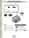
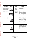
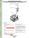

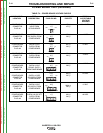

TRANSFORMER #1
3
/8” MOUNTING
SCREWS (2)
PLUG
P59
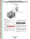
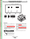
TRANSFORMER #1
3
/8” MOUNTING
SCREWS (2)
PLUG
P59
FIGURE F.8 – TEST LEAD LOCATIONS
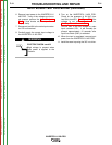
AUXILIARY TRANSFORMER NO. 1 TEST (continued)
PROCEDURE
1. Remove the main input supply power to the
INVERTEC® V450-PRO.
2. Using the 3/8 in. nut driver, remove the case
sides and top.
3. Perform the Capacitor Discharge Procedure.
4. Locate leads X8 and 41B at Power Board
Bridge.
5. Locate secondary leads X3 and X5 (fan motor
leads).
6. Locate secondary lead X4 (at main
contactor).
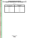
7. Carefully apply the correct input voltage to the
INVERTEC® V450-PRO and check for the cor-
rect secondary voltages per Table F.3.
NOTE: The secondary voltages will vary if the
input line volage varies.
8. If the secondary voltages are present, the T1
auxiliary transformer is functioning properly. If
any of the secondary voltages are missing or
low, check to make certain the primary is con-
figured correctly for the input voltage applied.
See Wiring Diagram.
9. If the correct voltage is applied to the primary,
and the secondary voltage(s) are not correct,
the T2 transformer may be faulty.
10. Install the case sides and top using the 3/8” nut
driver.
TROUBLESHOOTING AND REPAIR
F-36 F-36
INVERTEC® V450-PRO
Return to Section TOC Return to Section TOC Return to Section TOC Return to Section TOC
Return to Master TOC Return to Master TOC Return to Master TOC Return to Master TOC