


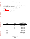


INPUT CONTACTOR TEST PROCEDURE (continued)
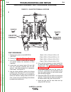
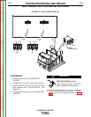
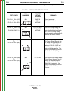
5. With the input contactor activated, check the
continuity across the three sets of contacts.
(Zero ohms or very low resistance is normal.)
See Figure F.5. If the resistance is high, the
input contactor is faulty. Replace the input con-
tactor.
6. When the contactor is NOT activated, the resis-
tance should be infinite or very high across the
contacts. If the resistance is low, the input con-
tactor is faulty.
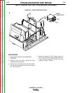
7. Reconnect the two leads (601, X4) to the input
contactor coil.
8. Install the input access door and case top using
the 3/8” nut driver.
TROUBLESHOOTING AND REPAIR
F-27 F-27
INVERTEC® V450-PRO
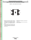
L3
L2
L1
T3
T2
T1
L3
L2
L1
T3
T2
T1
FIGURE F.5 – INPUT CONTACTOR TEST POINTS
Return to Section TOC Return to Section TOC Return to Section TOC Return to Section TOC
Return to Master TOC Return to Master TOC Return to Master TOC Return to Master TOC