


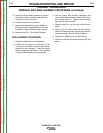
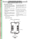

SWITCH BOARD
SWITCH BOARD
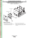
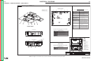
FIGURE F.23 – SWITCH BOARD LOCATION
SWITCH BOARD AND FILTER CAPACITOR
REMOVAL AND REPLACEMENT (continued)
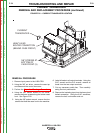
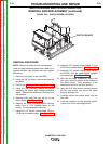
REMOVAL PROCEDURE
NOTE: Observe all static electricity precautions.
Lead and plug references below use a slash (/) to
indicate machine right side/left side wire number
differences.
1. Remove input power to the V450-PRO.
2. Using the 3/8” nut driver, remove the case top
and sides.
3. Perform the Capacitor Discharge Procedure.
4. Using the 3/8” nutdriver, remove the screw
mounting the plastic high voltage protective
shield. Remove the shield and it’s mount from
the machine.
5. Remove molex plug J50 from the top of the
switch board. See Figure F.24.
6. Remove the mylar insulating shield covering
leads 13/14 or 17/18 (marked clearly on the
board). Cut any necessary cable ties.
7. Using the 7/16” wrench, remove leads 13/14 or
17/18 from the switch board. See Figure F.24.
8. Using the 7/16” wrench, remove leads 11/12 or
15/16 from the switch board. See Figure F.24.
9. Using the 7/16” wrench, remove leads 19C/D+
and 20C/D- from the switch board capacitor
connection bolts. See Figure F.24.
10. With the slot head screwdriver, remove the
two nylon mounting screws at the bottom of
the switch board. Note placement of the
shake-proof washers and fiber spacers.
11. Using the 3/16” allen wrench, carefully remove
the four cap screws that mount the switch
board to the heat sink.
12. Carefully remove the switch board from the
heat sink.
13. If the filter capacitor is to be removed, careful-
ly slide it out of the mounting bracket.
TROUBLESHOOTING AND REPAIR
F-82 F-82
INVERTEC® V450-PRO
Return to Section TOC Return to Section TOC Return to Section TOC Return to Section TOC
Return to Master TOC Return to Master TOC Return to Master TOC Return to Master TOC