


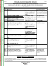


CAPACITOR
TERMINALS
RESISTOR
CAPACITOR
TERMINALS
RESISTOR
CAPACITOR
TERMINALS
RESISTOR
CAPACITOR
TERMINALS
RESISTOR
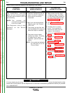
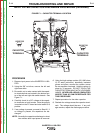
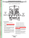
FIGURE F.1 – CAPACITOR TERMINAL LOCATION
INPUT FILTER CAPACITOR DISCHARGE PROCEDURE (continued)
PROCEDURE
1. Remove input power to the INVERTEC® V450-
PRO.
2. Using the 3/8” nut driver, remove the left and
right case sides.
3. Be careful not to make contact with the capaci-
tor terminals that are located in the bottom cen-
ter of the left and right side switch boards. See
Figure F.1.
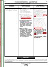
4. Carefully check for a DC voltage at the capaci-
tor terminals on both boards. Note the polarity
is marked on the PC board and also lead #19 is
positive.
5. If any voltage is present, proceed to Step #6. If
no voltage is present, the capacitors are dis-
charged.
NOTE: Normally the capacitors discharge in about
two minutes after input power is removed.
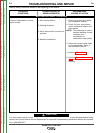
6. Using the high wattage resistor (25-1000 ohms
@ 25 watts (minimum), electrically insulated
gloves and pliers, connect the resistor across
the two capacitor terminals. Hold the resistor in
place for 10 seconds. DO NOT TOUCH THE
CAPACITOR TERMI-NALS WITH YOUR BARE
HANDS. NEVER USE A SOLID CONDUCTOR
W/LESS THAN 25 OHM RESISTANCE FOR
THIS PROCEDURE.
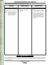
7. Repeat procedure for the other capacitor.
8. Recheck the voltage across the capacitor termi-
nals. The voltage should be zero. If any volt-
age remains, repeat the discharge procedure.
TROUBLESHOOTING AND REPAIR
F-14 F-14
INVERTEC® V450-PRO
Return to Section TOC Return to Section TOC Return to Section TOC Return to Section TOC
Return to Master TOC Return to Master TOC Return to Master TOC Return to Master TOC