


OUTPUTOUTPUT
M
PSMPS
AA
OLTSOLTS
VV
R
EMOTEREMOTE
L
OCALLOCAL
CONTROLCONTROL
SELECTSELECT
SOFT
CRIP
HI-FREQ
T
IG
T
OUCH
START
TIG
POSITIVE (+)
OUTPUT
TERMINAL
NEGATIVE (-)
OUTPUT
TERMINAL
OUTPUTOUTPUT
M
PSMPS
AA
OLTSOLTS
VV
R
EMOTEREMOTE
L
OCALLOCAL
CONTROLCONTROL
SELECTSELECT
SOFT
CRIP
HI-FREQ
T
IG
T
OUCH
START
TIG
POSITIVE (+)
OUTPUT
TERMINAL
NEGATIVE (-)
OUTPUT
TERMINAL
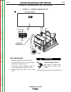
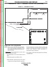
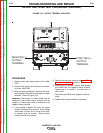
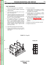
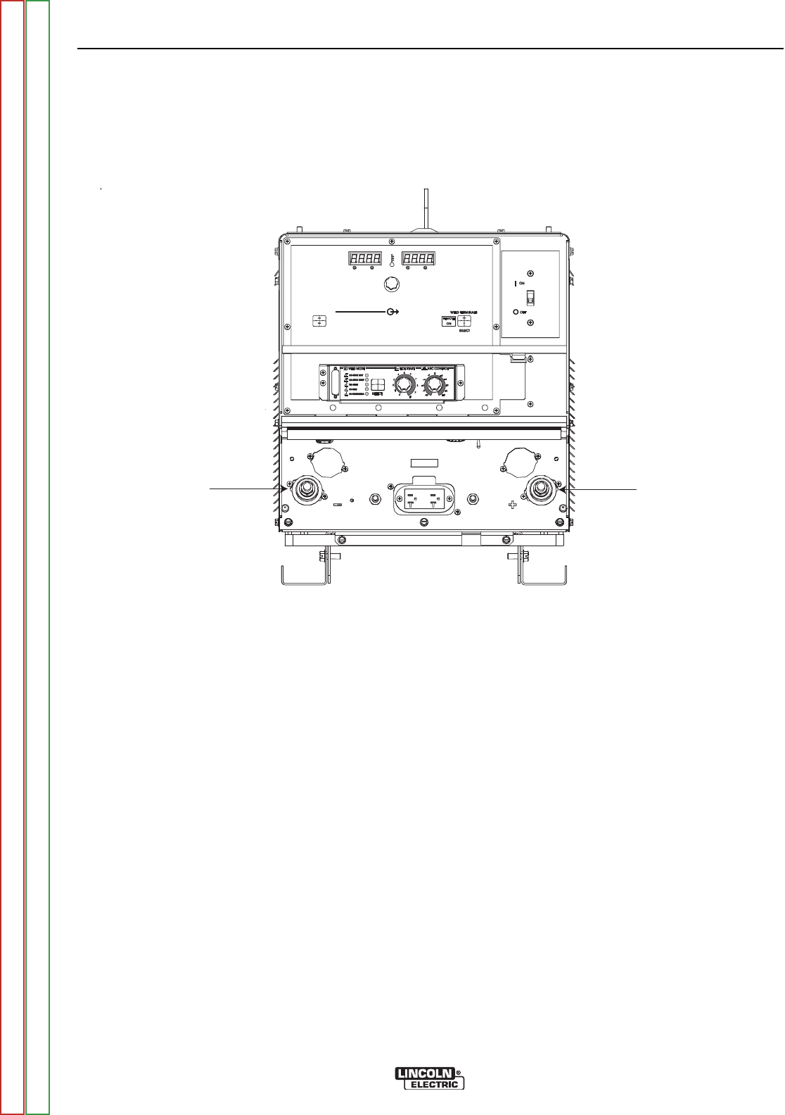
FIGURE F.13 - OUTPUT TERMINAL LOCATION
OUTPUT RECTIFIER TEST PROCEDURE (continued)
PROCEDURE
1. Remove main input supply power to the V450-
PRO.
2. Remove any output load that may be connect-
ed to the V450-PRO.
3. With the analog ohmmeter, measure the resis-
tance between the positive and negative output
terminals. Refer to Figure F.13.
Important: The positive (+) meter probe must be
attached to the positive output terminal and the
negative (-) meter probe must be attached to the
negative output terminal.
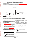
4. If the reading is approx. 50 ohms, the output
rectifier modules are not shorted. If the reading
is less than 10 ohms, one or more of the rectifi-
er modules may be shorted. Reverse meter
probe and verify low reading.
5. Remove the case top perform the Input Filter
Capacitor Discharge procedure.
6. Using the 5/16” wrench, remove and insulate
lead 202A from the negative output terminal.
Repeat step 4 to confirm if it is less than 10
ohms short.
7. Reconnect lead 202A to the negative output ter-
minal.
8. Replace the shorted modules if necessary.
TROUBLESHOOTING AND REPAIR
F-52 F-52
INVERTEC® V450-PRO
Return to Section TOC Return to Section TOC Return to Section TOC Return to Section TOC
Return to Master TOC Return to Master TOC Return to Master TOC Return to Master TOC