


J3
3
J3
3
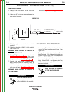
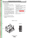
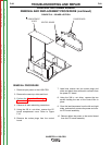
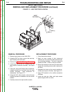
FIGURE F.15 - Plug J33
SPI CABLE RESISTANCE AND VOLTAGE TEST PROCEDURE (continued)
TEST PROCEDURE
1. Remove the input power to the V450-PRO.
2. Using the #2 Phillips screwdriver, remove the
case front panel.
5. Locate and remove plug J33 from the control
board. See Figure F.15.
6. Check the resistance and continuity of the SPI
cable by testing with the ohmmeter from each
pin on plug J33 to the corresponding pins on
plug J34. See the Wiring Diagram.
7. The resistance reading pin to corresponding
pin should be zero ohms or very low resis-
tance. If the resistance reading is high or
“open” check the plug connections to the SPI
network PC boards. If the connections are OK
and the resistance is high or “open” the SPI
cable may be faulty.
8. Reconnect the plug into the control board.
9. With plug J33 reinstalled in the control board,
carefully apply the correct input power to
V450-PRO.
TROUBLESHOOTING AND REPAIR
F-58 F-58
INVERTEC® V450-PRO
1
2
3
4
5
6
7
8
9
10
1
2
3
4
5
6
7
8
9
10
10. Turn on the machine.
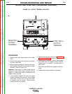
11. Carefully check for the presence of +15VDC
from plug J33 pin -1(+) to plug J33 pin -10(-) at
the display board receptacle.
12. Carefully check for the presence of +5VDC
from plug J33 pin -2(+) to plug J33 pin -10(-) at
the display board receptacle.
13. If either of these voltages are low or not pre-
sent, the control board may be faulty. Replace.
Also Perform the Power Board Test.
14. Remove the input power to the V450-PRO
machine.
15. Replace any cable ties previously removed.
16. Replace the case front.
PLUG J33
Return to Section TOC Return to Section TOC Return to Section TOC Return to Section TOC
Return to Master TOC Return to Master TOC Return to Master TOC Return to Master TOC