


F
r
o
n
t
T
i
l
t
s
F
o
r
w
a
r
d
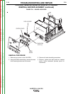
CONTROL BOARD
3/8” MOUNTING
BOLTS (4)
DISPLAY BOARD
MODE
BOARD
F
r
o
n
t
T
i
l
t
s
F
o
r
w
a
r
d
CONTROL BOARD
3/8” MOUNTING
BOLTS (4)
DISPLAY BOARD
MODE
BOARD
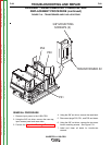
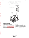
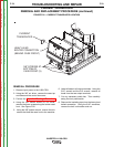
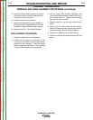
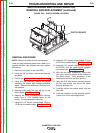
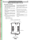
FIGURE F.21 – BOARD LOCATIONS
CONTROL, REMOTE, MODE OR DISPLAY PC BOARD
REMOVAL AND REPLACEMENT (continued)
REMOVAL PROCEDURE
1. Remove input power to the V450-PRO.
2. Using the Phillips screwdriver, remove the case
front mounting screws and tilt forward.
3. Observe all static electricity precautions.
4. Remove, replace and add panels as needed
and/or follow advanced process panel kit
instructions.
TROUBLESHOOTING AND REPAIR
F-76 F-76
INVERTEC® V450-PRO
Return to Section TOC Return to Section TOC Return to Section TOC Return to Section TOC
Return to Master TOC Return to Master TOC Return to Master TOC Return to Master TOC