


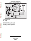
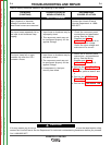
OUTPUT PROBLEMS
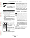
Observe Safety Guidelines detailed in the beginning of this manual.
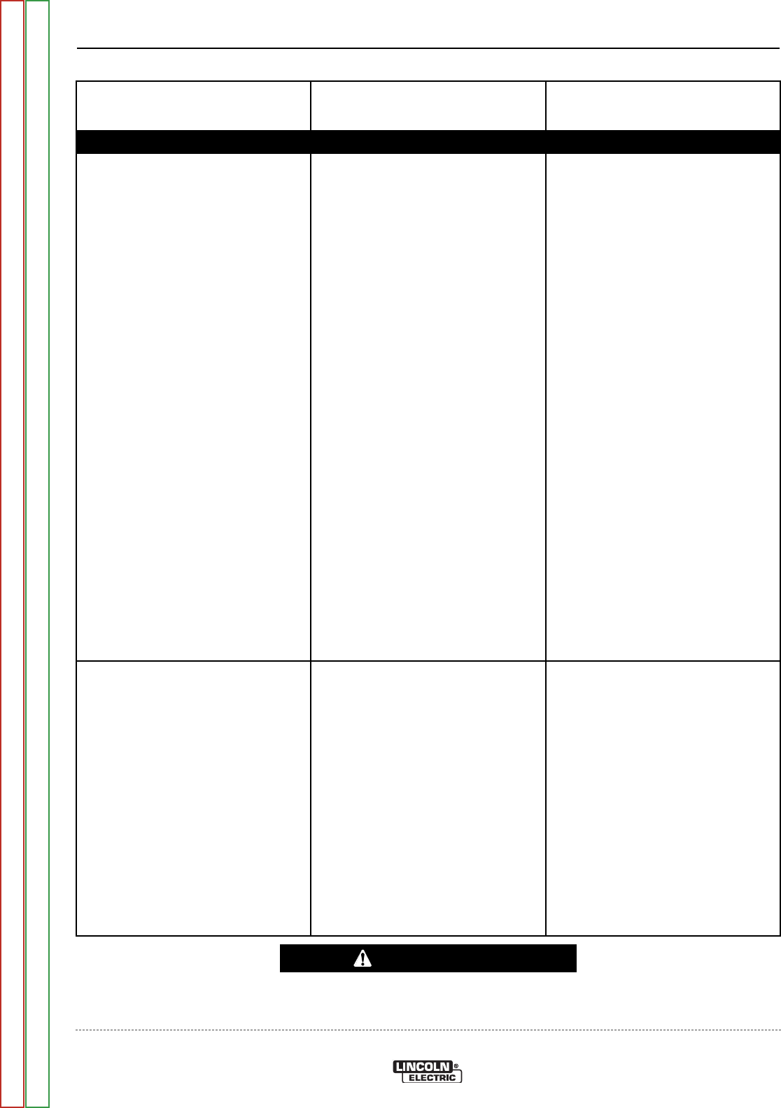
PROBLEMS
(SYMPTOMS)
POSSIBLE AREAS OF
MISADJUSTMENT(S)
RECOMMENDED
COURSE OF ACTION
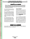
If for any reason you do not understand the test procedures or are unable to perform the tests/repairs safely,
contact the Lincoln Electric Service Department for technical troubleshooting assistance before you proceed.
Call 1-888-935-3877.
CAUTION
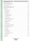
TROUBLESHOOTING AND REPAIR
F-5 F-5
INVERTEC® V450-PRO
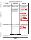
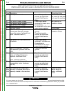
The machine is dead - - no lights
- - no output - - the machine
appears to have no power.
1. Make sure the input power
switch SW1 is in the ON
position.
2. Check the main input fuses or
breakers and make sure all
three phases are present.
3. Check the CB3 breaker
(located in the reconnect
area). Reset if tripped.
1. Check the input power switch
SW1 for proper operation.
Also check the associated
leads for loose or faulty
connections. See the Wiring
Diagram or Machine Diagram
for the welder in Section G.
2. Replace or reset input fuses
or breaker.
3. If CB-3 opens repeatedly,
perform the Auxiliary
Transformer Test.
4. The power board rectifier may
be faulty. Check the rectifier
and associated wiring. See
the Wiring Diagram or
Machine Diagram for the
welder in Section G.
5. Perform the Power Board
Test.
6. Perform the Control Board
Check. The Control Board
may be faulty.
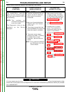
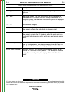
The Auxiliary Receptacle is “dead”.
No 120VAC present.
1. Check CB-2 on the case front.
Reset if necessary.
2. Check CB-3 in the reconnect
area. Reset if necessary.
3. Make sure all three input phases
are present
1. Check the receptacle and asso-
ciated wiring. See the Wiring
Diagram or Machine Diagram in
Section G.
2. Perform the Auxiliary
Transformer Test #2.
Return to Section TOC Return to Section TOC Return to Section TOC Return to Section TOC
Return to Master TOC Return to Master TOC Return to Master TOC Return to Master TOC