


SWITCH BOARD AND FILTER CAPACITOR
REMOVAL AND REPLACEMENT (continued)
REPLACEMENT PROCEDURE
1. If the filter capacitor is to be replaced, careful-
ly slide the new capacitor into the mounting
bracket. Position the capacitor so the correct
polarity terminal is lined up with the correct
hole on the switch board.
2. All heat sink and IGBT mounting surfaces
must be clean.
3. Apply a thin coat of thermal compound
(Penetrox A13) 0.005 to 0.010 inches thick to
the mating surfaces. Do not apply around
mounting holes.
4. Apply a thin coat of Penetrox A13 to the
capacitor terminals. Be careful not to apply
compound to screw threads or threaded area
of terminals.
5. Mount the new switch board and tighten the
four cap head screws in the following manner.
Tighten all until snug.
Tighten all from 24 to 28 in-lbs.
Tighten all from 40 to 48 in-lbs.
6. Make sure the capacitor is positioned correctly.
Connect leads 19C/D+ and 20C/D- to the cor-
rect terminals. Tighten to 55 in/lbs.
7. Position and mount the two nylon screws, fiber
spacers, and washers. Torque from 4 to 8 in-
lbs.
8. Connect leads 15/16 to the correct terminal.
9. Connect leads 17/18 to the correct terminal.
10. Install the mylar insulating shield covering
leads 15/16. Replace the cable tie.
11. Connect molex plug J40/J50 to the top of the
switch board.
12. Using the 5/16” nut driver, install the plastic
high voltage protective shield.
13. Install the case top and sides using the 3/8”
nut driver.
TROUBLESHOOTING AND REPAIR
F-83 F-83
INVERTEC® V450-PRO
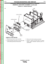
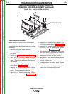
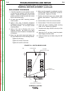
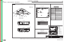
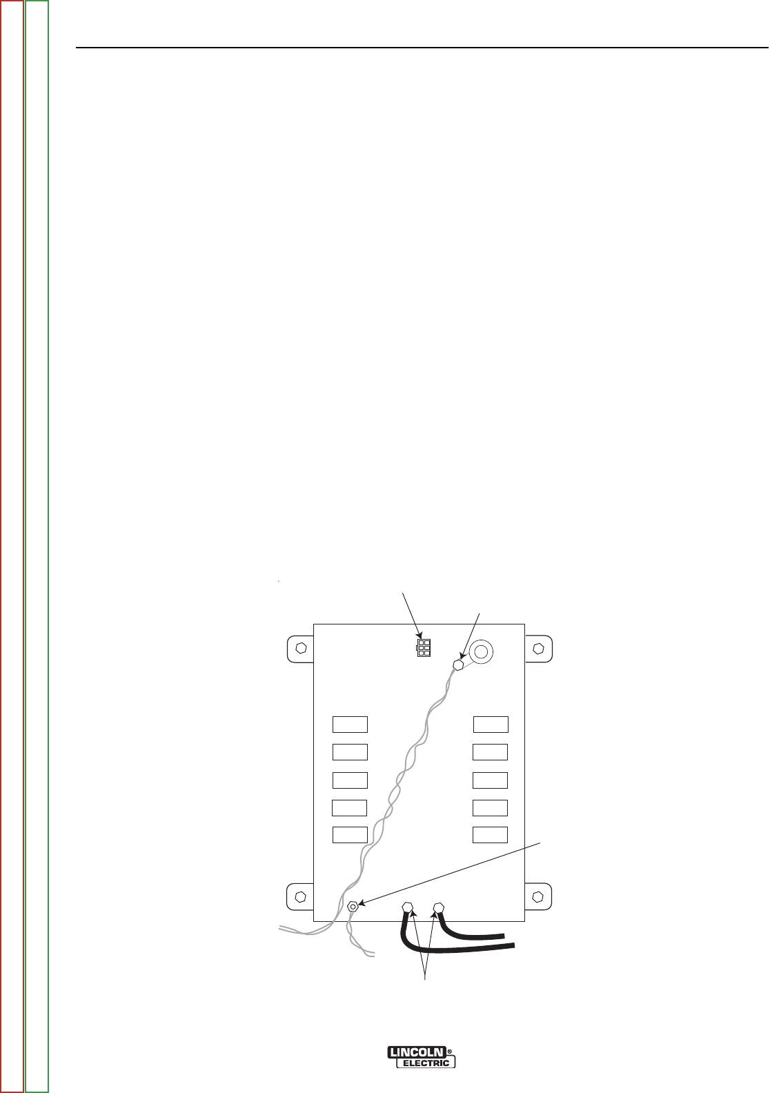
PLUG J40/J50
7/16” NUT
(Leads 13/14 or 17/18)
7/16” NUT
(Leads 11/12 or 15/16)
7/16” NUT
(Leads 19C/D+ and 20C/D-)
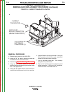
PLUG J40/J50
7/16” NUT
(Leads 13/14 or 17/18)
7/16” NUT
(Leads 11/12 or 15/16)
7/16” NUT
(Leads 19C/D+ and 20C/D-)
FIGURE F.24 – SWITCH BOARD LEADS
Return to Section TOC Return to Section TOC Return to Section TOC Return to Section TOC
Return to Master TOC Return to Master TOC Return to Master TOC Return to Master TOC