


INSTALLATION
A-4 A-4
INVERTEC® V450-PRO
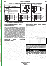
INPUT FUSE AND SUPPLY WIRE
CONSIDERATIONS
Refer to the Technical Specifications at the beginning
of this Installation section for recommended fuse and
wire sizes. Fuse the input circuit with the recommend-
ed super lag fuse or delay type breakers (also called
“inverse time” or “thermal/magnetic” circuit breakers).
Choose an input and grounding wire size according to
local or national electrical codes. Using fuses or circuit
breakers smaller than recommended may result in
“nuisance” shut-offs from welder inrush currents, even
if the machine is not being used at high currents.
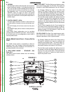
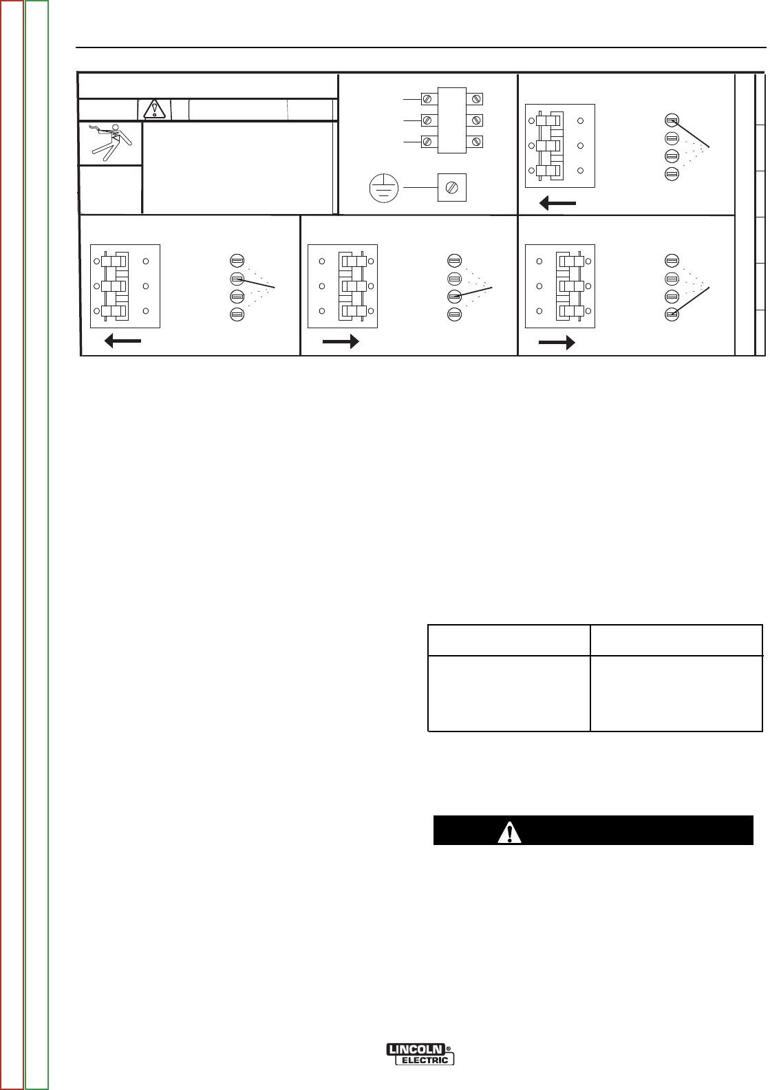
INPUT VOLTAGE CHANGE OVER (FOR
MULTIPLE INPUT VOLTAGE
MACHINES ONLY)
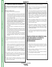
Welders are shipped connected for the highest input
voltage listed on the rating plate. To move this connec-
tion to a different input voltage, see the diagram locat-
ed on the inside of the input access door. If the main
reconnect switch or link position is placed in the wrong
position, the welder will not produce output power.
If the Auxiliary (A) lead is placed in the wrong position,
there are two possible results. If the lead is placed in a
position higher than the applied line voltage, the welder
may not come on at all. If the Auxiliary (A) lead is
placed in a position lower than the applied line voltage,
the welder will not come on, and the two circuit break-
ers or fuses in the reconnect area will open. If this
occurs, turn off the input voltage, properly connect the
(A) lead, reset the breakers, and try again. For
machines equipped with a fuse in the reconnect area,
turn off the input voltage and replace the fuse with the
spare fuse that is attached to the reconnect switch pin.
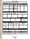
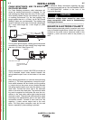
NOTE: Turn main input power to the machine OFF before performing connection procedure. Failure to do
so will result in damage to the machine.
FIGURE A.1 - CONNECTION DIAGRAM ON CONNECTION/INPUT ACCESS DOOR
200-208V
220-230V
440-460V
550-575V
200-208V
220-230V
=
220-230V
220-230V
200-208V
220-230V
440-460V
550-575V
200-208V
U / L1
550-575V
440-460V
'A'
'A'
= 440-460V
'A'
S25198
VOLTAGEVOLTAGE
VOLTAGE
VOLTAGE
=
200-208V
THE LINCOLN ELECTRIC CO. CLEVELAND, OHIO U.S.A.
XA
'A'
= 550-575V
CR1
W / L3
V / L2
440-460V
550-575V
.
inspecting or servicing machine.
Do not operate with covers
.
r
emoved.
Do not touch electrically live parts.
.
Only qualied persons should install,
use or service this equipment.
.
Disconnect input power before
INPUT SUPPLY CONNECTION DIAGRAM
WARNING
ELECTRIC
SHOCK
CAN KILL
200-208V
220-230V
440-460V
550-575V
200-208V
220-230V
=
220-230V
220-230V
200-208V
220-230V
440-460V
550-575V
200-208V
U / L1
550-575V
440-460V
'A'
'A'
= 440-460V
'A'
S25198
VOLTAGEVOLTAGE
VOLTAGE
VOLTAGE
=
200-208V
THE LINCOLN ELECTRIC CO. CLEVELAND, OHIO U.S.A.
XA
'A'
= 550-575V
CR1
W / L3
V / L2
440-460V
550-575V
.
inspecting or servicing machine.
Do not operate with covers
.
r
emoved.
Do not touch electrically live parts.
.
Only qualied persons should install,
use or service this equipment.
.
Disconnect input power before
INPUT SUPPLY CONNECTION DIAGRAM
WARNING
ELECTRIC
SHOCK
CAN KILL
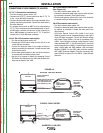
ELECTRODE AND WORK CABLE
CONNECTIONS
Connect a work lead of sufficient size and length (Per
Table 1) between the proper output terminal on the
power source and the work. Be sure the connection to
the work makes tight metal-to-metal electrical contact.
To avoid interference problems with other equipment
and to achieve the best possible operation, route all
cables directly to the work and wire feeder. Avoid
excessive lengths and do not coil excess cable.
Minimum work and electrode cable sizes are as follows:
TABLE A.1
(Current (60% Duty Cycle)
MINIMUM COPPER
WORK CABLE SIZE AWG
Up To-100 Ft. Length (30 m)
400 Amps 2/0 (67 mm
2
)
500 Amps 3/0 (85 mm
2
)
600 Amps 3/0 (85 mm
2
)
NOTE: K1796 coaxial welding cable is recommended
to reduce the cable inductance in long cable lengths.
This is especially important when Pulse welding up to
350 amps.
When using inverter type power sources like the
V450-PRO, use the largest welding (electrode and
work) cables that are practical. At least 2/0 (67
mm
2
) copper wire - even if the average output cur-
rent would not normally require it. When pulsing,
the pulse current can reach very high levels.
Voltage drops can become excessive, leading to
poor welding characteristics, if undersized welding
cables are used.
------------------------------------------------------------------------
CAUTION
Return to Section TOC Return to Section TOC Return to Section TOC Return to Section TOC
Return to Master TOC Return to Master TOC Return to Master TOC Return to Master TOC