


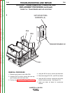


FIGURE F.20 – DOOR REMOVAL
AUXILIARY TRANSFORMER NO. 1 REMOVAL AND
REPLACEMENT PROCEDURE (continued)
REMOVAL PROCEDURE
1. Remove input power to the V450-PRO.
2. Using the 3/8” nut driver, remove the case top,
and input access panel.
3. Perform the Capacitor Discharge Procedure.
4. Using the 3/8” nut driver, remove the case back.
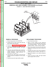
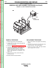
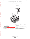
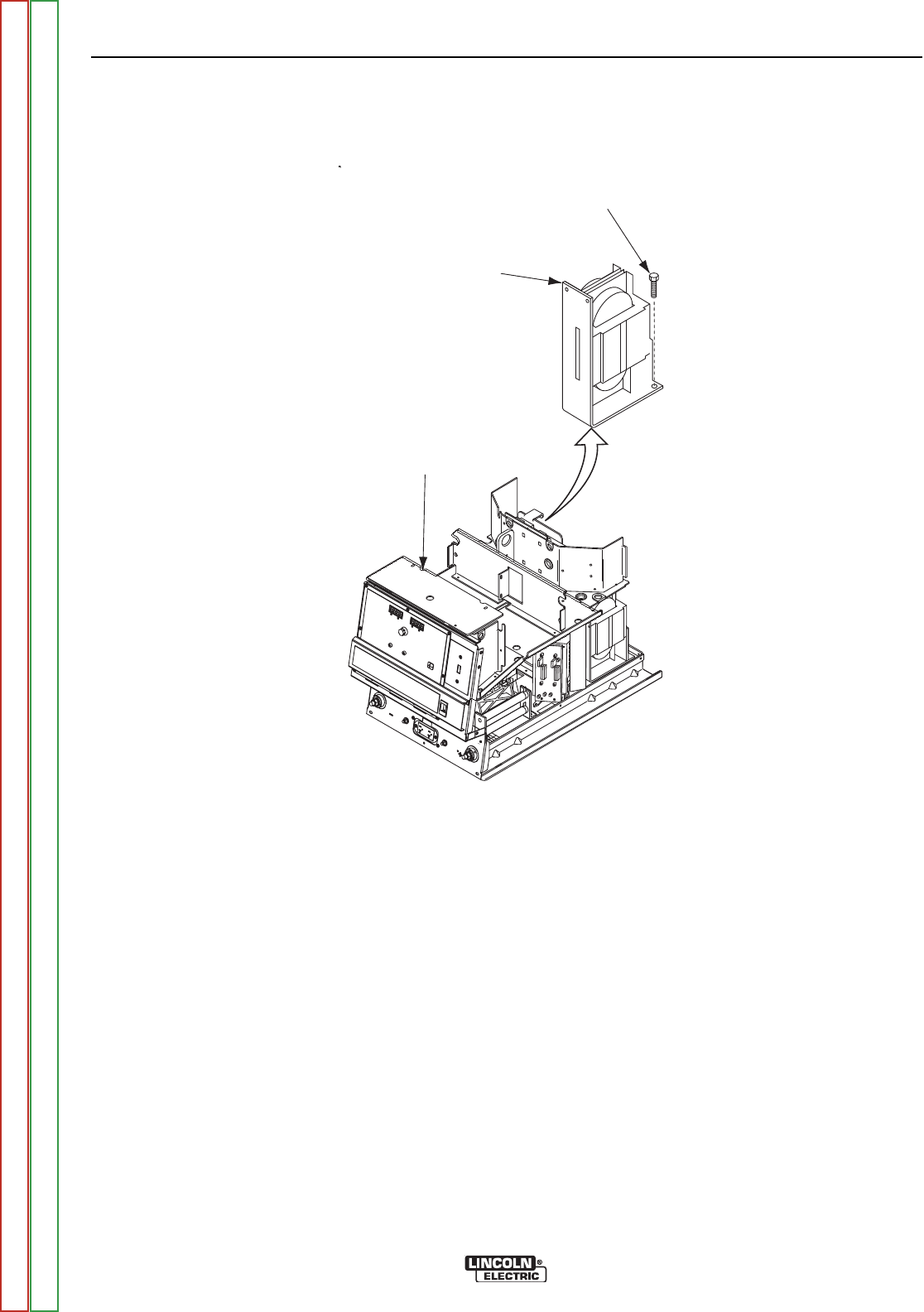
5. Remove leads 41B and unplug P59. See
Figure F.20.
6. Label and cut or remove all primary and sec-
ondary leads from transformer #1. See Wiring
Diagram.
7. Disconnect plug P59. See Figure F.20.
TROUBLESHOOTING AND REPAIR
F-72 F-72
INVERTEC® V450-PRO
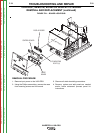
TRANSFORMER #1
3/8” MOUNTING
SCREWS (2)
PLUG
P59
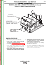
TRANSFORMER #1
3/8” MOUNTING
SCREWS (2)
PLUG
P59
Return to Section TOC Return to Section TOC Return to Section TOC Return to Section TOC
Return to Master TOC Return to Master TOC Return to Master TOC Return to Master TOC